Uncategorized

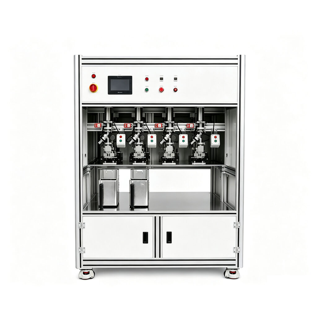
u shaped heat pipe vacuum machine

Heat Pipe Production Line: Equipment and Process Guide

Heat Pipe Production Line: Equipment and Process Guide 1. What Is a Heat Pipe Production Line? A Heat Pipe Production Line combines specialized machines for manufacturing heat pipes. It supports each major stage, from raw material preparation to final product testing. First, manufacturers prepare metal tubes and internal wick structures. Next, they process the tubes through filling, vacuum treatment, and sealing. Finally, they inspect finished products and evaluate thermal performance. Therefore, every manufacturing stage requires suitable equipment. Heat pipes transfer heat through evaporation and condensation. Inside each pipe, working fluid moves between hot and cold areas. This process requires suitable internal structures and controlled manufacturing conditions. Consequently, manufacturers must control cleanliness, vacuum levels, and fluid charging. A complete Heat Pipe Production Line helps factories coordinate these operations. Moreover, it supports consistent manufacturing and production planning. However, different heat pipe designs require different equipment configurations. Buyers should consider product dimensions, wick structures, and output targets. 2. How Does Heat Pipe Manufacturing Work? Heat pipe manufacturing combines mechanical processing, vacuum technology, and thermal testing. First, manufacturers prepare the metal tubes. Then, they install or form the internal wick structure. Next, the production process removes unwanted gases and moisture. Afterward, filling equipment introduces the working fluid. The welding system then seals the filling port. Finally, inspection equipment evaluates product quality and thermal performance. Each stage affects the final product. For example, poor internal cleanliness may reduce heat transfer performance. Similarly, inaccurate fluid charging may affect thermal operation. Therefore, manufacturers need reliable equipment and suitable process controls. A coordinated production line connects these operations. As a result, factories can manage production more efficiently. 3. Main Equipment in a Heat Pipe Production Line A complete manufacturing setup may include several specialized machines. However, the exact configuration depends on product design and production capacity. 3.1 Heat Pipe Tube Cutting Machine Tube cutting prepares raw materials for further processing. First, the machine cuts metal tubes to specified lengths. Then, operators inspect the cutting surface and dimensions. Accurate cutting improves consistency during later operations. Additionally, clean tube ends support reliable processing. Manufacturers should consider tube materials, diameters, and cutting requirements. 3.2 Heat Pipe Necking Machine A necking machine reduces the diameter of selected tube sections. This operation prepares tube ends for later filling and sealing. Moreover, controlled necking helps maintain consistent dimensions. Manufacturers should match the machine with tube materials and sizes. They should also consider tooling requirements for different product models. Suggested internal link: Heat Pipe Necking Machine 3.3 Heat Pipe Powder Filling Machine Some heat pipes use sintered metal powder as their wick structure. A powder filling machine introduces metal powder into the tube. The filling process should support consistent material distribution. Uneven powder distribution may affect the final wick structure. Therefore, manufacturers should evaluate filling accuracy and process stability. Suggested internal link: Heat Pipe Powder Filling Machine 3.4 Vacuum Sintering Furnace A vacuum sintering furnace forms the porous wick structure. First, the furnace heats the filled tube under controlled conditions. Then, metal particles bond together and create a porous structure. This structure supports working fluid circulation. Consequently, sintering quality affects heat pipe performance. Manufacturers should evaluate temperature control and vacuum requirements. They should also confirm compatibility with their materials and product designs. Suggested internal link: Vacuum Sintering Furnace 3.5 Heat Pipe Vacuum Degassing Machine Degassing removes unwanted gases and moisture from the internal space. First, the machine connects the heat pipe to a vacuum system. Then, it removes residual gases under controlled conditions. Proper degassing supports stable internal operating conditions. Therefore, vacuum performance deserves careful attention. Some production lines use dedicated degassing equipment. Other configurations combine degassing with filling and sealing operations. Suggested internal link: Heat Pipe Vacuum Degassing Machine 3.6 Heat Pipe Filling & Welding Machine This machine introduces working fluid and seals the heat pipe. First, the system prepares the required vacuum conditions. Next, it introduces a controlled amount of working fluid. Then, the machine seals the filling port through a suitable welding process. Manufacturers must control fluid quantity and sealing quality. Suggested internal link: Heat Pipe Filling & Welding Machine 3.7 Heat Pipe Multi-Station Dry-Out Tester A multi-station dry-out tester evaluates heat pipe behavior under thermal loads. It allows manufacturers to test several samples during the same production cycle. Therefore, it can support batch inspection and quality control. The test helps manufacturers identify performance problems. For example, they can evaluate whether a heat pipe handles its intended heat load. Suggested internal link: Heat Pipe Multi-Station Dry-Out Tester 3.8 Heat Pipe Thermal Performance Tester Thermal performance testing verifies heat pipe behavior under defined conditions. Manufacturers use this equipment to evaluate heat transfer characteristics. In addition, they can compare different product designs. Testing supports product development and quality management. However, test conditions must reflect the intended application. Suggested internal link: Heat Pipe Thermal Performance Tester 4. Step-by-Step Heat Pipe Manufacturing Process A typical manufacturing process includes several major stages. However, product structure and factory requirements may change the sequence. Step 1: Raw Material Preparation First, manufacturers select suitable metal tubes. Copper and other compatible materials serve different product requirements. Next, operators cut tubes to the required dimensions. They should also inspect the material surface. This step helps identify defects before further processing. Step 2: Wick Structure Preparation The wick structure supports working fluid circulation. Depending on the design, manufacturers may use sintered powder or other wick structures. Therefore, equipment selection must match the chosen manufacturing method. Step 3: Powder Filling and Sintering For powder-based designs, manufacturers introduce metal powder into the tube. Next, a vacuum sintering furnace processes the material. This operation forms the porous wick structure. The resulting structure supports fluid movement inside the heat pipe. Consequently, powder quality and sintering conditions matter. Step 4: Internal Cleaning and Degassing Internal cleanliness affects heat pipe performance. Therefore, manufacturers remove contaminants before final filling. Vacuum degassing also removes unwanted gases and moisture. This stage helps prepare the internal environment for working fluid charging. Step 5: Working Fluid Filling Each heat pipe requires a suitable

Heat Pipe Production Line: Equipment and Process Guide Read More »
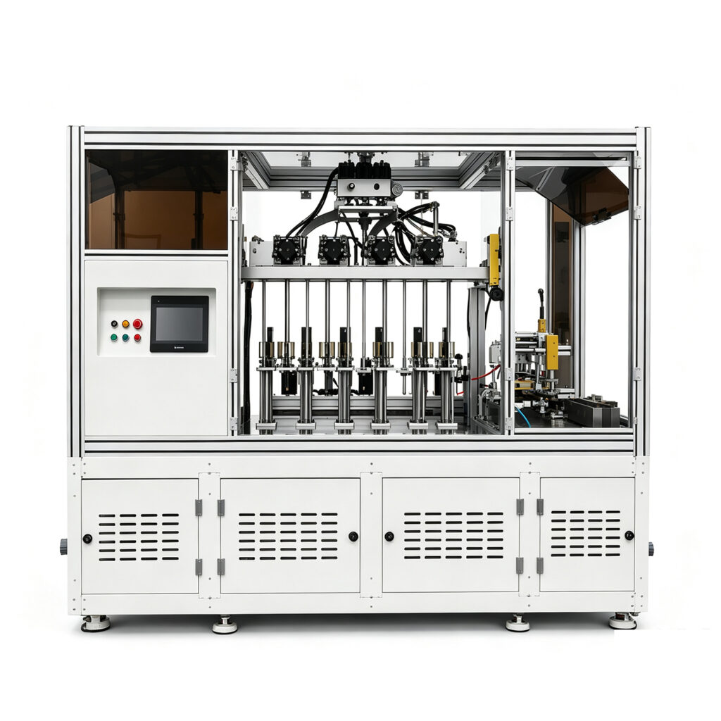
automatic secondary degassing & tail welding machine for heat pipe

Heat Pipe Equipment Production Line: Complete Guide

Heat Pipe Equipment Production Line: Complete Guide 1. What Is a Heat Pipe Equipment Production Line? A Heat Pipe Equipment Production Line combines specialized machines for manufacturing heat pipes. It supports every major production stage, from tube preparation to final inspection. First, manufacturers prepare metal tubes and internal wick structures. Next, they process the tubes through filling, vacuum treatment, and sealing. Finally, they inspect finished products and evaluate thermal performance. Therefore, each machine plays an important role in product quality. Heat pipes transfer heat through evaporation and condensation. Inside each pipe, working fluid moves between hot and cold areas. This process requires suitable internal structures and controlled manufacturing conditions. Consequently, manufacturers need reliable equipment for every critical operation. A complete production line helps factories organize these operations. Moreover, it supports consistent manufacturing and production planning. However, different heat pipe designs require different equipment configurations. Buyers should consider product dimensions, wick structures, and output targets. 2. How Does Heat Pipe Equipment Work? Heat pipe equipment supports several connected manufacturing processes. Each machine handles a specific operation. First, tube preparation equipment cuts and shapes metal tubes. Then, powder filling equipment introduces materials for suitable wick structures. Next, sintering equipment processes the powder under controlled conditions. Afterward, vacuum equipment removes unwanted gases and moisture. The filling system introduces the working fluid. Meanwhile, welding equipment seals the filling port. Finally, testing equipment evaluates product quality and thermal performance. These operations require careful coordination. For example, poor powder distribution may affect wick performance. Similarly, inaccurate fluid charging may reduce heat transfer efficiency. Therefore, manufacturers should select compatible equipment across the entire process. 3. Essential Machines in a Heat Pipe Production Line A complete Heat Pipe Equipment Production Line may include several specialized machines. However, the exact configuration depends on the manufacturing process. 3.1 Heat Pipe Tube Cutting Machine Tube cutting prepares raw materials for further processing. First, the machine cuts metal tubes to specified lengths. Then, operators check the cutting surface and dimensions. Accurate cutting improves consistency during later operations. Additionally, clean tube ends support reliable processing. Manufacturers should consider tube materials, diameters, and cutting requirements. 3.2 Heat Pipe Necking Machine A necking machine reduces the diameter of selected tube sections. This operation prepares tube ends for subsequent filling and sealing. Moreover, controlled necking helps maintain consistent dimensions. The machine should match the required tube materials and sizes. Manufacturers should also consider tooling changes between product models. Suggested internal link: Heat Pipe Necking Machine 3.3 Heat Pipe Powder Filling Machine Some heat pipes use sintered metal powder as their wick structure. A powder filling machine introduces metal powder into the tube. The filling process should support consistent material distribution. Uneven powder distribution may affect the final wick structure. Therefore, manufacturers should evaluate filling accuracy and process stability. Suggested internal link: Heat Pipe Powder Filling Machine 3.4 Vacuum Sintering Furnace A vacuum sintering furnace forms the porous wick structure. First, the furnace heats the filled tube under controlled conditions. Then, metal particles bond together and create a porous structure. This structure supports working fluid circulation. Consequently, sintering quality affects heat pipe performance. Manufacturers should evaluate temperature control and vacuum requirements. They should also confirm compatibility with their materials and product designs. Suggested internal link: Vacuum Sintering Furnace 3.5 Heat Pipe Vacuum Degassing Machine Degassing removes unwanted gases and moisture from the internal space. First, the machine connects the heat pipe to a vacuum system. Then, it removes residual gases under controlled conditions. Proper degassing supports stable internal operating conditions. Therefore, vacuum performance deserves careful attention. Some production lines use dedicated degassing equipment. Other configurations combine degassing with filling and sealing operations. Suggested internal link: Heat Pipe Vacuum Degassing Machine 3.6 Heat Pipe Filling & Welding Machine This machine introduces working fluid and seals the heat pipe. First, the system prepares the required vacuum conditions. Next, it introduces a controlled amount of working fluid. Then, the machine seals the filling port through a suitable welding process. Manufacturers must control fluid quantity and sealing quality. Suggested internal link: Heat Pipe Filling & Welding Machine 3.7 Heat Pipe Multi-Station Dry-Out Tester A multi-station dry-out tester evaluates heat pipe behavior under thermal loads. It allows manufacturers to test several samples during the same production cycle. Therefore, it can support batch inspection and quality control. The test helps manufacturers identify performance problems. For example, they can evaluate whether a heat pipe handles its intended heat load. Suggested internal link: Heat Pipe Multi-Station Dry-out Tester 3.8 Heat Pipe Thermal Performance Tester Thermal performance testing verifies heat pipe behavior under defined conditions. Manufacturers use this equipment to evaluate heat transfer characteristics. In addition, they can compare different product designs. Testing supports product development and quality management. However, test conditions must reflect the intended application. Suggested internal link: Heat Pipe Thermal Performance Tester 4. Heat Pipe Manufacturing Process A typical manufacturing process includes several major stages. However, product structure and factory requirements may change the sequence. Step 1: Raw Material Preparation First, manufacturers select suitable metal tubes. Copper and other compatible materials serve different product requirements. Next, operators cut tubes to the required dimensions. They should also inspect the material surface. This step helps identify defects before further processing. Step 2: Wick Structure Preparation The wick structure supports working fluid circulation. Depending on the design, manufacturers may use sintered powder or other wick structures. Therefore, equipment selection must match the chosen manufacturing method. Step 3: Powder Filling and Sintering For powder-based designs, manufacturers introduce metal powder into the tube. Next, a vacuum sintering furnace processes the material. This operation forms the porous wick structure. The resulting structure supports fluid movement inside the heat pipe. Consequently, powder quality and sintering conditions matter. Step 4: Internal Cleaning and Degassing Internal cleanliness affects heat pipe performance. Therefore, manufacturers remove contaminants before final filling. Vacuum degassing also removes unwanted gases and moisture. This stage helps prepare the internal environment for working fluid charging. Step 5: Working Fluid Filling Each heat pipe requires a suitable working fluid. Manufacturers

Heat Pipe Equipment Production Line: Complete Guide Read More »

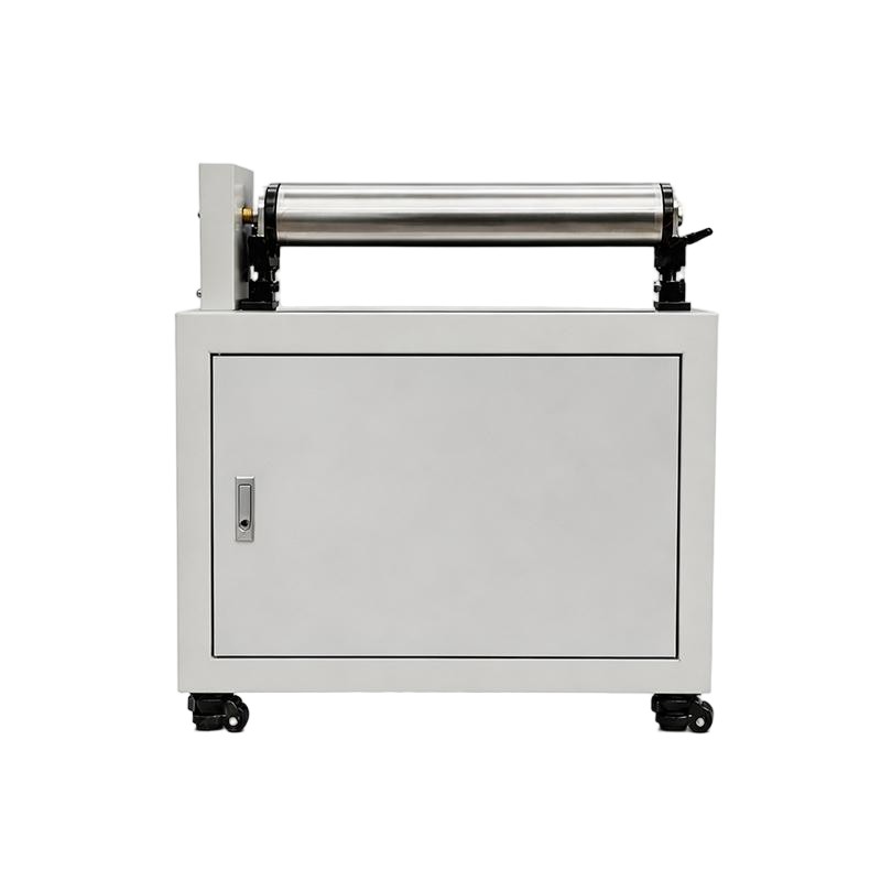
heat pipe straightening machine

Heat Pipe Production Line: Complete Manufacturing Guide

Heat Pipe Production Line: Complete Manufacturing Guide 1. What Is a Heat Pipe Production Line? A Heat Pipe Production Line combines machines for manufacturing heat pipes. It supports several production stages, from tube preparation to final testing. First, manufacturers prepare metal tubes and internal structures. Next, they install the working fluid and seal each pipe. Finally, they test product quality and thermal performance. A complete production line helps manufacturers organize these operations. Moreover, it improves process consistency and production efficiency. Heat pipes transfer heat through evaporation and condensation. Therefore, manufacturers must control internal cleanliness, vacuum conditions, and fluid charging. Each production stage affects the final product. Consequently, equipment selection plays an important role in manufacturing quality. A suitable production line also supports different product designs. For example, manufacturers may produce straight, bent, or flattened heat pipes. However, each design requires suitable processing methods. Therefore, buyers should evaluate their product requirements before selecting equipment. 2. How Does Heat Pipe Manufacturing Work? Heat pipe manufacturing combines mechanical processing, vacuum technology, and thermal testing. First, manufacturers prepare the metal tube. Then, they install the wick structure and clean the internal surface. Afterward, the production process removes unwanted gases and moisture. Next, operators introduce the correct working fluid. The machine then seals the tube. Finally, manufacturers inspect the finished product and verify its thermal performance. Each step requires suitable equipment and process control. For instance, poor cleaning may affect internal heat transfer. Similarly, inaccurate fluid charging may reduce thermal performance. Therefore, a coordinated Heat Pipe Production Line helps manufacturers control important production variables. 3. Key Equipment in a Heat Pipe Production Line A complete manufacturing setup may include several specialized machines. However, the exact configuration depends on product design and production capacity. 3.1 Heat Pipe Tube Cutting Machine Tube cutting prepares raw materials for further processing. First, the machine cuts metal tubes to the required length. Then, operators inspect the cutting surface and dimensions. Accurate cutting improves consistency during later operations. Additionally, clean tube ends support reliable sealing. 3.2 Heat Pipe Necking Machine A necking machine reduces the diameter of selected tube sections. This process prepares the tube for subsequent filling and sealing. Moreover, controlled necking helps maintain consistent dimensions. Manufacturers should match the machine design with tube materials and sizes. 3.3 Heat Pipe Powder Filling Machine Some heat pipes use sintered powder wick structures. A powder filling machine introduces metal powder into the tube. Next, the manufacturer prepares the powder for sintering. The filling process requires consistent material distribution. Therefore, manufacturers should consider filling accuracy and production stability. Suggested internal link: Heat Pipe Powder Filling Machine 3.4 Vacuum Sintering Furnace A vacuum sintering furnace forms the porous wick structure. First, the furnace heats the filled tube under controlled conditions. Then, metal particles bond together and create a porous structure. This structure supports working fluid circulation. Consequently, sintering quality affects heat pipe performance. Manufacturers should evaluate furnace temperature control and vacuum requirements. Suggested internal link: Vacuum Sintering Furnace 3.5 Heat Pipe Vacuum Degassing Machine Degassing removes unwanted gases and moisture from the internal space. First, the machine connects the heat pipe to a vacuum system. Then, it removes residual gases under controlled conditions. Proper degassing supports stable internal operation. Therefore, vacuum performance deserves careful attention. Some manufacturing processes use dedicated degassing equipment. Others integrate degassing with filling and sealing operations. Suggested internal link: Heat Pipe Vacuum Degassing Machine 3.6 Heat Pipe Filling & Welding Machine The filling and welding process introduces working fluid and closes the pipe. First, the system prepares the required vacuum conditions. Next, it introduces a controlled amount of working fluid. Then, the machine seals the filling port through a suitable welding process. Manufacturers must control both fluid quantity and sealing quality. Suggested internal link: Heat Pipe Filling & Welding Machine 3.7 Heat Pipe Multi-Station Dry-Out Tester Dry-out testing evaluates heat pipe behavior under thermal loads. A multi-station tester allows manufacturers to evaluate several samples. Therefore, it can support batch inspection and production quality control. The test helps identify performance problems. For example, manufacturers can investigate whether a pipe handles its intended heat load. Suggested internal link: Heat Pipe Multi-Station Dry-Out Tester 3.8 Heat Pipe Thermal Performance Tester Thermal performance testing verifies product behavior under defined conditions. Manufacturers use this equipment to evaluate heat transfer characteristics. In addition, they can compare different product designs. Testing helps manufacturers maintain consistent product quality. However, test conditions must match the intended application. Suggested internal link: Heat Pipe Thermal Performance Tester 4. Main Manufacturing Steps A typical heat pipe manufacturing process follows several stages. However, product structure and manufacturing methods may change the sequence. Step 1: Prepare the Metal Tubes First, manufacturers select suitable tube materials. Copper and other compatible metals serve different product requirements. Next, operators cut the tubes to the specified dimensions. They also check surface condition and dimensional accuracy. Step 2: Install the Wick Structure The wick structure supports working fluid circulation. Depending on the design, manufacturers may use metal powder or other wick structures. Therefore, the production method must match the selected design. Step 3: Fill and Sinter the Powder For sintered wick designs, manufacturers introduce metal powder into the tube. Next, a vacuum sintering furnace processes the powder. This operation forms the porous structure inside the heat pipe. Step 4: Clean and Degas the Tube Internal cleanliness affects manufacturing quality. Therefore, manufacturers remove contaminants before final filling. The vacuum degassing process also removes unwanted gases and moisture. Step 5: Introduce the Working Fluid Each heat pipe requires a suitable working fluid. Manufacturers select the fluid according to operating temperatures and application requirements. Then, filling equipment introduces the required quantity. Accurate charging supports stable thermal operation. However, the correct amount depends on the product design. Step 6: Seal the Heat Pipe After fluid charging, manufacturers close the filling port. A suitable welding system creates the final seal. Operators should inspect the sealing area and follow the required quality procedures. Step 7: Test the Finished Product Finally, manufacturers inspect the finished

Heat Pipe Production Line: Complete Manufacturing Guide Read More »

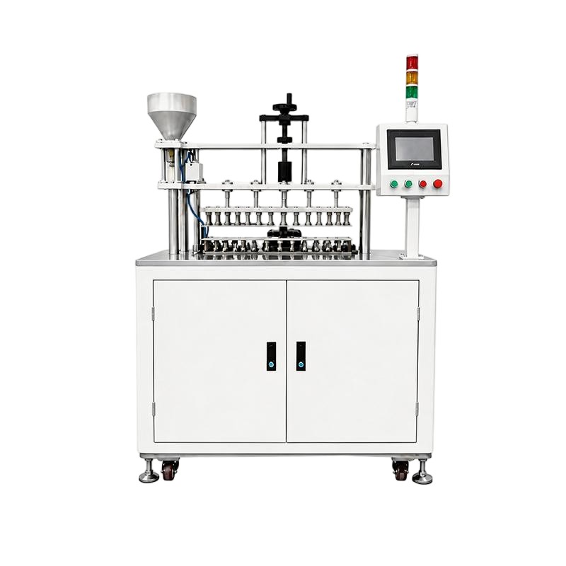
heat pipe powder filling machine

Heat Pipe Equipment Production Line: Complete Guide

Heat Pipe Equipment Production Line: Complete Guide 1. What Is a Heat Pipe Equipment Production Line? A Heat Pipe Equipment Production Line is a coordinated collection of machines used to manufacture heat pipes for thermal management applications. It covers the main production stages, from metal tube preparation to final product inspection. Each machine performs a specific task. Together, they create a repeatable manufacturing process. Heat pipes transfer thermal energy through evaporation and condensation. They provide efficient heat transfer in compact structures. Manufacturers use them in computers, servers, LED lighting, power electronics, and industrial cooling systems. However, heat pipe production requires more than basic tube processing. Manufacturers must control internal wick structures, cleanliness, moisture, vacuum conditions, working-fluid quantity, and sealing quality. A suitable production line helps organize these operations. It can also reduce manual handling and improve manufacturing consistency. Depending on the product design, a complete line may include: Copper tube cutting machine Heat Pipe Necking Machine Heat Pipe Powder Filling Machine Vacuum Sintering Furnace Heat Pipe Multi-station Dry-out Tester Heat Pipe Vacuum Degassing Machine Heat Pipe Filling & Welding Machine Heat Pipe Leak Tester Heat Pipe Thermal Performance Tester Not every manufacturer needs all these machines. The equipment configuration depends on the wick structure, tube dimensions, production volume, and automation requirements. Therefore, manufacturers should define their product specifications before purchasing equipment. 2. How Does Heat Pipe Manufacturing Work? Understanding the heat pipe operating principle helps explain why each manufacturing stage matters. A heat pipe is a sealed thermal transfer device. It contains a working fluid and an internal wick structure. Its operation involves three main stages. 2.1 Evaporation First, heat enters the evaporator section. The working fluid absorbs thermal energy and changes from liquid into vapor. This process transfers energy through the vapor phase. 2.2 Vapor Movement Next, the vapor moves toward the cooler condenser section. The vapor transports thermal energy along the internal passage. This allows the heat pipe to transfer heat efficiently across a relatively small structure. 2.3 Condensation and Liquid Return At the condenser section, vapor releases heat and condenses into liquid. The internal wick structure helps return the liquid toward the evaporator through capillary action. This cycle continues during normal operation. Common wick structures include: Sintered copper powder wick Grooved wick Mesh wick Composite wick Each structure requires different manufacturing methods. For example, sintered powder wicks need controlled powder filling and sintering processes. Consequently, the selected Heat Pipe Equipment Production Line must match the intended wick design. 3. Essential Equipment for Heat Pipe Manufacturing A complete heat pipe manufacturing system combines tube preparation, wick processing, drying, vacuum treatment, filling, sealing, and inspection equipment. The following machines represent common equipment categories. 3.1 Copper Tube Cutting Machine The cutting machine prepares copper tubes according to the required dimensions. Accurate cutting helps maintain consistent product length. It also provides suitable tube ends for later forming and sealing operations. Manufacturers should evaluate cutting accuracy, burr control, tube diameter compatibility, and production speed. For high-volume manufacturing, automatic feeding and cutting functions can reduce repetitive manual work. 3.2 Heat Pipe Necking Machine A Heat Pipe Necking Machine reduces the tube diameter at selected sections. This operation prepares the tube for subsequent manufacturing steps. It may also create suitable sealing areas. The machine must match the tube material, wall thickness, and required necking dimensions. Manufacturers should pay attention to forming accuracy. Excessive deformation can damage the tube or affect its internal space. 3.3 Heat Pipe Powder Filling Machine Some heat pipes use sintered copper powder as their internal wick structure. A Heat Pipe Powder Filling Machine introduces copper powder into the tube. The process must control powder quantity and distribution. Consistent powder filling helps prepare the internal structure for sintering. Important selection factors include: Powder filling accuracy Tube diameter compatibility Filling method Production capacity Fixture design Cleaning and maintenance requirements Manufacturers should select a machine that matches the required wick structure and product range. 3.4 Vacuum Sintering Furnace A Vacuum Sintering Furnace bonds metal powder particles through controlled heating. For sintered wick heat pipes, this process creates a porous internal structure. The structure supports capillary liquid return during operation. Vacuum conditions help control the processing atmosphere. Temperature and holding time must match the material and wick design. Manufacturers should validate the sintering recipe to achieve consistent wick characteristics. They should also consider furnace capacity, temperature uniformity, loading methods, and maintenance requirements. 3.5 Heat Pipe Multi-station Dry-out Tester Drying removes residual moisture and volatile substances from prepared heat pipe components. A multi-station design allows several components to undergo processing within the same operating cycle or across multiple processing positions. Controlled drying helps prepare heat pipes for later evacuation and working-fluid charging. The required temperature and drying duration depend on product design and process conditions. For production applications, manufacturers should evaluate station capacity, temperature control, loading convenience, and process repeatability. 3.6 Heat Pipe Vacuum Degassing Machine A Heat Pipe Vacuum Degassing Machine helps remove unwanted gases and volatile substances from the internal space. This operation supports preparation before working-fluid charging and final sealing. Manufacturers should evaluate vacuum performance, pumping capacity, connection design, and process stability. The required vacuum conditions depend on the heat pipe specification and manufacturing method. 3.7 Heat Pipe Filling & Welding Machine The filling and welding machine introduces the specified working fluid and seals the heat pipe. Working-fluid quantity is a critical manufacturing parameter. An unsuitable charge can affect thermal performance and operating stability. The welding process must also produce a reliable seal. Manufacturers should evaluate: Filling accuracy Working-fluid compatibility Welding method Sealing consistency Process control functions Product changeover requirements A suitable machine helps manufacturers control two important operations within a coordinated workflow. 3.8 Heat Pipe Leak Tester A Heat Pipe Leak Tester checks the integrity of the sealed heat pipe. Leak testing helps identify leakage that could affect internal pressure or working-fluid retention. Depending on the product and factory process, manufacturers may use pressure-based, vacuum-based, or tracer-gas testing methods. The selected method should meet the required inspection sensitivity and product

Heat Pipe Equipment Production Line: Complete Guide Read More »

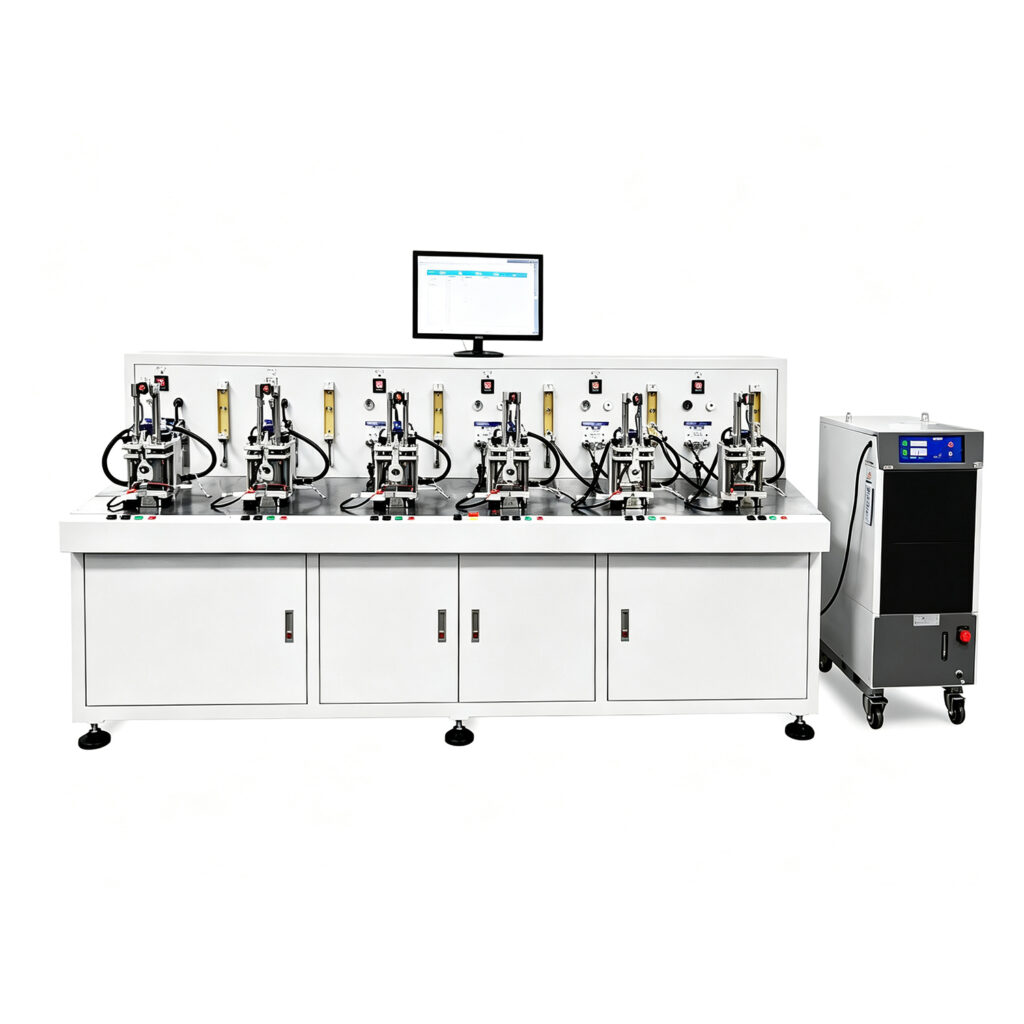
automatic heat pipe production line

Heat Pipe Production Line: Complete Manufacturing Guide

Heat Pipe Production Line: Complete Manufacturing Guide 1. What Is a Heat Pipe Production Line? A Heat Pipe Production Line is an integrated manufacturing system designed to produce heat pipes for thermal management applications. It combines several specialized machines into one coordinated production workflow. Each machine performs a specific operation, from copper tube preparation to final product testing. Heat pipes transfer thermal energy through evaporation and condensation. They offer excellent heat transfer capabilities within relatively compact structures. Manufacturers use heat pipes in computers, servers, LED lighting, power electronics, and industrial cooling systems. However, producing reliable heat pipes requires precise manufacturing processes. Tube dimensions, wick structures, internal cleanliness, working-fluid quantity, and sealing quality all influence final performance. A complete Heat Pipe Production Line helps manufacturers control these processes. It also supports consistent production across different batches. A typical production line may include: Copper tube cutting machines Heat Pipe Necking Machines Heat Pipe Powder Filling Machines Vacuum Sintering Furnaces Heat Pipe Multi-station Dry-out Testers Heat Pipe Vacuum Degassing Machines Heat Pipe Filling & Welding Machines Heat Pipe Leak Testers Heat Pipe Thermal Performance Testers Not every factory needs all these machines. The final configuration depends on product structure, production capacity, automation requirements, and manufacturing methods. For example, manufacturers producing sintered wick heat pipes need suitable powder filling and sintering equipment. Meanwhile, other wick structures may require different preparation processes. Therefore, equipment selection should begin with the actual product specifications. 2. How Does a Heat Pipe Work? Understanding the operating principle helps manufacturers understand each production stage. A heat pipe is a sealed thermal transfer device. It contains a working fluid and an internal wick structure. Its operation involves three main stages. 2.1 Evaporation First, heat enters the evaporator section of the heat pipe. The working fluid absorbs thermal energy and changes from liquid into vapor. This process transfers heat through the vapor phase. 2.2 Vapor Movement Next, vapor moves toward the cooler condenser section. The vapor transports thermal energy along the internal passage. This allows the heat pipe to transfer heat efficiently between different locations. 2.3 Condensation and Liquid Return At the condenser section, vapor releases heat and changes back into liquid. The internal wick structure helps return the liquid toward the evaporator through capillary action. This cycle continues during normal operation. The wick structure plays an important role in heat pipe performance. Common designs include: Sintered copper powder wick Grooved wick Mesh wick Composite wick Each structure has different manufacturing requirements. Therefore, manufacturers must select suitable equipment for their chosen heat pipe design. 3. Main Equipment in a Heat Pipe Production Line A complete Heat Pipe Production Line combines equipment for tube preparation, wick formation, drying, vacuum treatment, fluid filling, sealing, and inspection. The following machines represent common equipment categories. 3.1 Copper Tube Cutting Machine The cutting machine prepares copper tubes according to the required dimensions. Accurate cutting helps maintain consistent product length. It also provides suitable tube ends for later forming and sealing operations. Manufacturers should evaluate cutting accuracy, burr control, tube diameter compatibility, and production speed. 3.2 Heat Pipe Necking Machine A Heat Pipe Necking Machine reduces the tube diameter at selected sections. This operation prepares the tube for subsequent manufacturing steps. It may also create suitable sealing areas. The machine must match the tube material, wall thickness, and required necking dimensions. 3.3 Heat Pipe Powder Filling Machine Some heat pipes use sintered copper powder as their internal wick structure. A Heat Pipe Powder Filling Machine introduces copper powder into the tube. The process must control powder quantity and distribution. Consistent powder filling helps prepare the internal structure for sintering. Manufacturers should consider filling accuracy, tube compatibility, and production efficiency when selecting this equipment. 3.4 Vacuum Sintering Furnace A Vacuum Sintering Furnace bonds metal powder particles through controlled heating. For sintered wick heat pipes, this process creates a porous internal structure. The structure supports capillary liquid return during operation. Vacuum conditions help control the processing atmosphere. Temperature and holding time must match the material and wick design. Manufacturers should validate the sintering recipe to achieve consistent wick characteristics. 3.5 Heat Pipe Multi-station Dry-out Tester Drying removes residual moisture and volatile substances from prepared heat pipe components. A multi-station design allows several components to undergo processing within the same operating cycle or across multiple processing positions. Controlled drying helps prepare heat pipes for later evacuation and working-fluid charging. The required temperature and drying duration depend on product design and process conditions. 3.6 Heat Pipe Vacuum Degassing Machine A Heat Pipe Vacuum Degassing Machine helps remove unwanted gases and volatile substances from the internal space. This operation supports preparation before working-fluid charging and final sealing. Manufacturers should evaluate vacuum performance, pumping capacity, connection design, and process stability. The required vacuum conditions depend on the heat pipe specification. 3.7 Heat Pipe Filling & Welding Machine The filling and welding machine introduces the specified working fluid and seals the heat pipe. Working-fluid quantity is a critical manufacturing parameter. An unsuitable charge can affect thermal performance and operating stability. The welding process must also produce a reliable seal. Manufacturers should evaluate filling accuracy, welding quality, process control, and compatibility with different heat pipe models. 3.8 Heat Pipe Leak Tester A Heat Pipe Leak Tester checks the integrity of the sealed heat pipe. Leak testing helps identify leakage that could affect internal pressure or working-fluid retention. Depending on the product and factory process, manufacturers may use pressure-based, vacuum-based, or tracer-gas testing methods. The selected method should meet the required inspection sensitivity. 3.9 Heat Pipe Thermal Performance Tester A Heat Pipe Thermal Performance Tester evaluates the heat transfer capability of finished products. Testing parameters may include heat input, temperature distribution, thermal resistance, and operating orientation. These results help manufacturers verify product performance against technical requirements. A consistent testing method also makes production quality easier to monitor. 4. Heat Pipe Manufacturing Process Step by Step The manufacturing sequence depends on the heat pipe design and selected production method. A typical process for a copper heat pipe

Heat Pipe Production Line: Complete Manufacturing Guide Read More »

heat pipe performance testing machine

Heat Pipe Powder Filling Machine for Precision Production

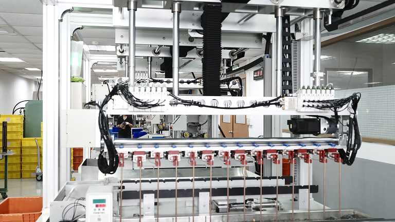
Heat Pipe Powder Filling Machine for Precision Production 1. What Is a Heat Pipe Powder Filling Machine? A Heat Pipe Powder Filling Machine is specialized manufacturing equipment used to load metal powder into heat pipe tubes during wick production. The powder forms the raw material for a porous wick structure after a suitable forming and sintering process. Heat pipes transfer thermal energy through the evaporation and condensation of an internal working fluid. Inside the sealed tube, the wick structure helps return condensed liquid toward the heated area through capillary action. The wick plays an important role in heat pipe operation. Its material, pore structure, thickness, and permeability influence liquid circulation and thermal performance. Copper powder is common in copper-water heat pipes. Manufacturers place the powder inside a prepared tube and then use a suitable process to form a porous structure. Depending on the design, this may involve mandrels, vibration, compaction, and sintering. A dedicated powder filling machine helps control how manufacturers introduce powder into the tube. It can reduce manual handling and improve filling consistency across production batches. However, powder filling is only one stage of wick manufacturing. The final wick quality also depends on powder characteristics, forming conditions, sintering parameters, and process control. 2. Why Powder Filling Matters in Heat Pipe Manufacturing Powder filling directly influences the material distribution inside the heat pipe. Inconsistent filling can create variations in wick thickness, density, and structure. These variations may affect capillary performance and the finished product’s heat-transfer capability. 2.1 Building the Porous Wick Structure A sintered powder wick contains interconnected pores. These pores allow liquid working fluid to move through the heat pipe. The powder must form a suitable structure after sintering. Particle size, particle shape, and distribution all influence the resulting pore characteristics. A powder filling machine helps deliver the material into the designated tube section. Manufacturers must still validate the subsequent forming and sintering processes. 2.2 Maintaining Consistent Powder Quantity Different heat pipe designs require different powder quantities. The required amount depends on tube dimensions, wick thickness, powder properties, and the intended structure. Too little powder may produce an insufficient wick layer. Excessive powder can reduce the available vapor space or create an unsuitable wick geometry. Accurate dosing helps manufacturers maintain consistent material quantities. It also makes production records easier to compare. 2.3 Supporting Uniform Powder Distribution Powder should reach the intended area without creating significant gaps or unwanted accumulation. Uneven distribution may lead to inconsistent wick structures after sintering. A suitable filling system can improve repeatability. The machine configuration should match the tube length, diameter, and powder characteristics. 2.4 Reducing Manual Handling Manual powder loading can create variation between operators and production batches. It may also increase material loss and workplace dust. A dedicated machine can standardize material delivery and reduce repetitive handling. Suitable dust collection and material containment also help maintain a cleaner production environment. 3. How a Heat Pipe Powder Filling Machine Works The working sequence depends on the equipment design and wick manufacturing method. A typical powder filling process includes several stages. 3.1 Powder Preparation Manufacturers first prepare the metal powder according to the product specification. They should control particle size distribution, cleanliness, moisture, and material consistency. For copper-water heat pipes, copper powder is a common wick material. Other designs may use different materials depending on operating conditions and product requirements. Powder preparation matters because material variation can influence filling behavior and the final sintered structure. 3.2 Tube Loading and Positioning The operator places the prepared heat pipe tube into the machine fixture. The fixture holds the tube in the correct position during powder loading. Accurate positioning helps direct powder into the intended section. It also supports consistent filling across different workpieces. 3.3 Powder Metering The machine delivers a specified quantity of powder into the tube. Depending on the design, the system may use controlled feeding, volumetric dosing, or another metering arrangement. The suitable method depends on powder flow characteristics and required filling accuracy. Manufacturers should verify the actual powder quantity through weighing or another validated measurement method. They should not assume that identical machine settings always produce identical powder mass. 3.4 Powder Distribution and Compaction Some wick designs require additional steps to distribute or compact the powder inside the tube. Equipment may use vibration, mechanical movement, or dedicated tooling. These operations help position the powder before sintering. The correct approach depends on the desired wick geometry and manufacturing process. 3.5 Transfer to the Sintering Process After filling and any required forming operation, manufacturers transfer the workpiece to a suitable sintering furnace. The furnace heats the powder under controlled conditions. This process bonds particles together while retaining a porous structure. Sintering parameters depend on powder composition, particle size, tube material, and wick design. Manufacturers should establish these parameters through process development and validation. For related equipment, consider linking to the 🔗 Vacuum Sintering Furnace page, if available on Linkthermal. 4. Common Powder Filling Methods Different heat pipe products require different powder loading arrangements. Machine selection should reflect the intended wick structure and production volume. 4.1 Controlled Powder Dosing Controlled dosing delivers a measured quantity of powder into each tube. This approach helps manufacturers maintain material consistency. It can suit production processes where each product model has a defined powder charge. The dosing system must also handle the powder’s flow characteristics. 4.2 Vibration-Assisted Filling Some processes use vibration to help powder move through a tube and settle into the required area. Vibration settings require careful validation. Excessive vibration may cause unwanted powder compaction or segregation, depending on the material and geometry. 4.3 Multi-Station Powder Filling A multi-station system can support several workpieces during a production cycle. This configuration may improve output when the loading and filling operations allow parallel processing. However, actual productivity depends on the number of stations, filling time, operator handling, and downstream equipment capacity. 4.4 Customized Filling Solutions Long tubes, small-diameter tubes, and special wick structures may require customized fixtures or feeding arrangements. Manufacturers should provide sample tubes and powder specifications before

Heat Pipe Powder Filling Machine for Precision Production Read More »

automatic heat pipe heating degasser machine

Heat Pipe Necking Machine for Precision Tube Forming

Heat Pipe Necking Machine for Precision Tube Forming 1. What Is a Heat Pipe Necking Machine? A Heat Pipe Necking Machine is specialized equipment that reduces the diameter of a selected section of a heat pipe tube. It creates a narrower end or transition area while maintaining the required tube shape and dimensions. Manufacturers use necking to prepare heat pipe tubes for later operations. These operations may include sealing, filling, welding, or connection with other components. The exact purpose depends on the heat pipe design. Heat pipes transfer thermal energy through the evaporation and condensation of an internal working fluid. Their performance depends on the sealed enclosure, wick structure, working fluid, and internal operating conditions. During manufacturing, tube dimensions must meet the requirements of the finished product. A necking machine helps control local tube deformation and supports repeatable component preparation. For manufacturers producing copper heat pipes, compact cooling assemblies, or customized thermal components, controlled necking can improve production consistency. It also reduces dependence on manual tube forming. However, necking parameters must match the tube material, wall thickness, diameter, and product geometry. Excessive deformation may damage the tube or affect its internal structure. 2. Why Necking Matters in Heat Pipe Manufacturing Necking is more than a simple tube-reduction operation. It prepares the heat pipe for subsequent manufacturing steps and helps maintain dimensional accuracy. 2.1 Preparing Tube Ends for Sealing Some heat pipe designs require a reduced tube section near the filling end. This section can provide a suitable area for later pinching, welding, or sealing. The necking process creates the required geometry before those operations. Consistent dimensions can make downstream positioning and joining easier. 2.2 Supporting Compact Product Designs Thermal management products often have limited installation space. Engineers may design heat pipes with different diameters along their length. A necked section can help the tube fit a specific assembly or connection. It can also support transitions between different component sizes. 2.3 Improving Dimensional Consistency Manual tube forming can produce variations between workpieces. A dedicated machine helps standardize the forming process. Manufacturers can define suitable tooling and process parameters for each product model. This approach supports repeatable tube dimensions and reduces unnecessary adjustments. 2.4 Protecting Tube Integrity Heat pipes use thin-walled metal tubes in many applications. The necking process must reduce the diameter without causing cracks, wrinkles, excessive thinning, or unwanted deformation. Manufacturers should validate the forming process using the actual tube material and dimensions. They should also inspect the finished section before moving to later production stages. 3. How a Heat Pipe Necking Machine Works The operating sequence depends on the machine structure and the required tube geometry. A typical process includes the following steps. 3.1 Tube Loading and Positioning The operator places the prepared tube into the machine fixture. The fixture holds the workpiece and positions the target area under the forming mechanism. Accurate positioning determines where the necked section begins and ends. It also helps maintain consistent forming length across different workpieces. 3.2 Clamping and Alignment The machine secures the tube before forming begins. Proper clamping prevents unwanted movement during the necking operation. The fixture should support the tube without creating excessive surface pressure. Alignment also matters because an offset workpiece may produce an uneven reduction. 3.3 Diameter Reduction The forming mechanism applies controlled force to the selected tube section. Depending on the machine design, it may use dies, rollers, or another forming structure. The tooling gradually reduces the outside diameter to the required dimension. The process should avoid sudden deformation that could damage the tube wall. 3.4 Forming Release and Unloading After reaching the target geometry, the machine releases the workpiece. The operator or automatic handling system then removes the formed tube. The machine may support manual loading, semi-automatic operation, or automated production. The appropriate configuration depends on output requirements and product variation. 3.5 Dimensional Inspection Manufacturers should inspect the necked section after forming. Typical checks include: Reduced outside diameter. Necking length. Transition shape. Concentricity and alignment. Surface condition. Evidence of cracks, wrinkles, or excessive thinning. Inspection criteria should come from the product drawing and approved process specifications. 4. Common Heat Pipe Necking Methods Different forming methods suit different tube materials and product geometries. Buyers should understand the available methods before selecting equipment. 4.1 Die-Based Necking Die-based necking uses shaped tooling to reduce the tube diameter. The tube enters a forming die that creates the required reduced section. This method can support repeatable geometry when the tooling matches the tube dimensions. It is suitable for production processes that use consistent product designs. Tool design, material properties, and forming force all influence the final result. 4.2 Roller Necking Roller necking uses rotating or moving rollers to form the tube. The rollers gradually reduce the diameter along the selected section. This approach may suit certain tube geometries and production requirements. However, the tooling arrangement must provide stable support and consistent deformation. 4.3 Custom Forming Solutions Some heat pipe designs require special transitions, short necking lengths, or non-standard end shapes. These applications may need customized tooling or forming arrangements. Manufacturers should provide drawings and representative samples before equipment selection. This allows the supplier to evaluate tooling compatibility and process feasibility. 5. Key Features to Consider When comparing a Heat Pipe Necking Machine, focus on the machine’s ability to meet your actual product requirements. 5.1 Supported Tube Dimensions Check the supported tube diameter, wall thickness, length, and material range. These factors determine whether the machine can handle your current products. If you manufacture several heat pipe models, ask about tooling changes and setup time. Do not assume one fixture can support every tube size. 5.2 Necking Accuracy The machine should produce the required reduced diameter and forming length. Ask the supplier how the system controls the forming position and final dimensions. Also confirm the inspection method used during sample testing. Dimensional results should match your engineering drawings. 5.3 Adjustable Forming Parameters Different tube materials may require different forming conditions. Adjustable settings can help operators adapt the machine to approved product specifications.

Heat Pipe Necking Machine for Precision Tube Forming Read More »

automatic heat pipe production line

Heat Pipe Filling & Welding Machine for Production

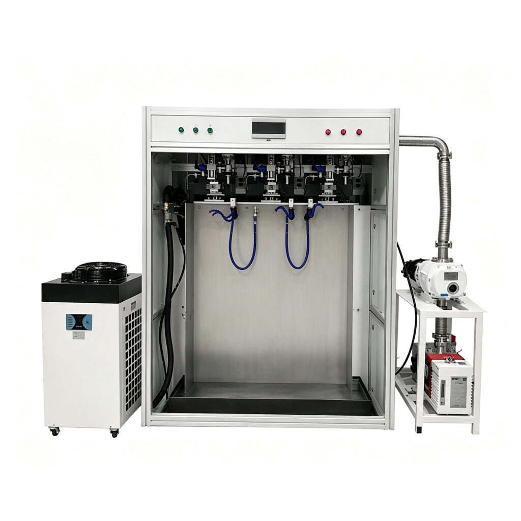
Heat Pipe Filling & Welding Machine for Production 1. What Is a Heat Pipe Filling & Welding Machine? A Heat Pipe Filling & Welding Machine is industrial equipment that supports two important stages of heat pipe manufacturing: working-fluid filling and tube sealing. Depending on the machine design, it may also support evacuation, positioning, and other process-control functions. Heat pipes transfer heat through the evaporation and condensation of a working fluid inside a sealed enclosure. Their performance depends on several factors, including the internal wick structure, working fluid, vacuum condition, and manufacturing quality. During production, manufacturers must introduce the correct amount of working fluid. They must also seal the tube without compromising its integrity. A suitable filling and welding machine helps control these operations and improve production consistency. For manufacturers serving electronics, power equipment, automotive, and industrial cooling markets, process stability matters. Even small variations in fluid charge or sealing quality can affect product performance and reliability. A modern machine can help standardize these operations, reduce manual handling, and improve traceability. However, the exact functions depend on the machine configuration and the requirements of each heat pipe design. 2. Why Filling and Welding Matter in Heat Pipe Manufacturing Heat pipe production requires precise control over several connected processes. Filling and welding deserve particular attention because they directly affect the sealed internal environment. 2.1 Accurate Working-Fluid Filling A heat pipe requires a suitable working fluid and charge quantity. The correct amount depends on the tube dimensions, wick structure, internal volume, and intended operating conditions. Too little fluid may limit evaporation and condensation performance. Too much fluid can also create problems under certain operating conditions. A controlled filling system helps manufacturers deliver repeatable fluid quantities. It can also reduce variation between production batches. 2.2 Reliable Tube Sealing After the required internal conditions and fluid charge have been established, manufacturers must close the filling port or designated tube section. The welding process must create a durable seal while protecting the surrounding tube. Poor welding can cause leakage or damage the tube. Excessive heat may also affect nearby components or sensitive structures, depending on the product design. A properly configured welding process helps maintain consistent sealing quality. Manufacturers should validate welding parameters for each relevant tube material, wall thickness, and joint design. 2.3 Stable Internal Conditions Heat pipes commonly rely on a controlled internal environment. Non-condensable gases can interfere with heat transfer, so evacuation and degassing procedures may form part of the manufacturing process. The filling and welding machine should fit the overall process sequence. Some systems combine multiple functions, while others operate alongside dedicated vacuum and degassing equipment. For related equipment, consider linking to the 🔗 Vapor Chamber Vacuum Filling & Welding Machine or 🔗 Heat Pipe Production Line, where these pages are available on your website. 3. How a Heat Pipe Filling & Welding Machine Works The exact workflow depends on the heat pipe structure, working fluid, and sealing method. However, most production systems coordinate several essential operations. 3.1 Workpiece Loading and Positioning Operators load prepared heat pipes into the machine’s fixtures. The fixtures must hold each tube securely and align the filling port with the connection or welding head. Accurate positioning helps prevent fluid leakage during filling. It also supports repeatable welding conditions. For high-volume production, manufacturers may prefer fixtures that accommodate multiple workpieces. The correct configuration depends on tube dimensions, product variation, and target output. 3.2 Evacuation and Internal Preparation Before filling, manufacturers generally remove unwanted gases from the heat pipe. A vacuum system can reduce residual air inside the tube and help establish the required internal conditions. Some applications also require heating or extended evacuation to remove residual moisture and gases. The appropriate procedure depends on the materials and working fluid. Research on two-phase thermal devices highlights the importance of removing internal air and non-condensable gases. These gases can obstruct condensation and reduce heat-transfer performance. PubMed Central (PMC)+1 3.3 Working-Fluid Filling Once the required conditions are established, the machine introduces the specified working fluid. The filling system should deliver a repeatable charge based on the product’s validated process parameters. Different heat pipe designs may require different filling methods. Liquid filling, vapor-based charging, and specialized procedures may apply to different fluids and operating temperatures. For this reason, manufacturers should confirm compatibility between the filling system and the intended working fluid. They should also consider fluid purity, material compatibility, and contamination control. 3.4 Tube Pinching and Welding After filling, the machine prepares the designated filling section for permanent closure. Depending on the design, this may involve pinching, cutting, welding, or another validated sealing method. Some systems use crimping followed by welding. Others may use a suitable cold-welding or pinch-off method. The selected process must create a durable seal without damaging the tube or disturbing its internal condition. Material type and tube-wall thickness influence the appropriate method. ScienceDirect Topics+1 3.5 Inspection and Process Confirmation Manufacturers should verify the finished heat pipe after filling and sealing. Inspection may include visual checks, leak testing, charge verification, and thermal performance testing. A filling and welding machine does not automatically replace these quality-control steps. Instead, it helps create repeatable manufacturing conditions that downstream tests can verify. 4. Key Features to Consider When comparing a Heat Pipe Filling & Welding Machine, evaluate its process capabilities rather than focusing on the equipment name alone. 4.1 Controlled Filling Accuracy Filling accuracy is one of the most important selection criteria. The machine should support the charge quantity required by your heat pipe design. Ask the supplier how the system measures and controls fluid delivery. Also, confirm how operators can check filling consistency during production. 4.2 Vacuum System Compatibility The vacuum system should match the required process conditions. Consider pump configuration, connection design, monitoring methods, and maintenance access. Do not judge the entire process by a vacuum reading alone. Residual moisture, material outgassing, and dissolved gases may also affect the internal environment. A validated process should account for these factors where relevant. 4.3 Suitable Welding Technology The welding method must match

Heat Pipe Filling & Welding Machine for Production Read More »

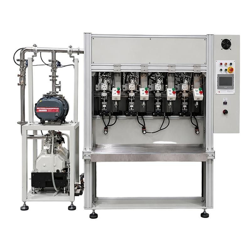
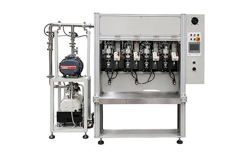
heat pipe secondary degasser high vacuum degassing for vc heat pipe manufacturing

Heat Pipe Multi-station Dry-out Tester Guide

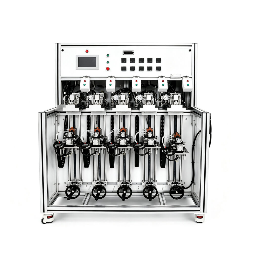
Heat Pipe Multi-station Dry-out Tester Guide 1. What Is a Heat Pipe Multi-station Dry-out Tester? A Heat Pipe Multi-station Dry-out Tester is specialized equipment for removing residual moisture and volatile contaminants from heat pipe components before subsequent manufacturing steps. Heat pipes transfer heat through the evaporation and condensation of a working fluid. Their performance depends on the internal structure, cleanliness, vacuum conditions, and working fluid. Therefore, manufacturers must carefully control the preparation process before sealing and filling each heat pipe. Moisture inside a heat pipe can affect internal pressure and interfere with stable operation. Contaminants can also influence fluid behavior and long-term reliability. A dry-out tester helps manufacturers control this critical preparation stage. Depending on its design, the equipment uses controlled heating, vacuum conditions, or other drying methods to remove residual moisture. The term multi-station indicates that the machine provides several processing positions. These stations can allow operators to process multiple heat pipes or components within the same production cycle. Consequently, a multi-station design can improve throughput compared with equipment that handles only one component at a time. However, actual capacity depends on the number of stations, heating performance, loading method, cycle duration, and process requirements. Manufacturers should evaluate these factors before selecting equipment for their production facilities. 2. Why Is the Dry-out Process Important? Drying is an essential preparation step in many heat pipe manufacturing processes. It helps establish suitable internal conditions before working-fluid charging and final sealing. 2.1 Removing Residual Moisture Moisture can remain inside metal tubes, capillary structures, and porous wick materials after cleaning or other manufacturing operations. If manufacturers do not remove sufficient moisture, residual water can affect the internal environment after sealing. The resulting impact depends on the working fluid, operating temperature, internal pressure, and product design. A controlled dry-out process helps reduce this risk. It also provides a more repeatable preparation procedure for subsequent manufacturing steps. 2.2 Supporting Vacuum and Filling Processes Many heat pipe manufacturing methods require evacuation before working-fluid charging. Residual moisture and volatile substances can complicate evacuation. They may also increase the time needed to reach the required process conditions. Proper drying helps prepare components for later vacuum treatment and filling. However, drying does not replace vacuum evacuation. Manufacturers should treat drying, evacuation, working-fluid charging, and sealing as separate process stages unless their equipment combines these functions. 2.3 Improving Process Consistency Manual drying can create variations in heating time, temperature exposure, and component handling. A properly configured Heat Pipe Multi-station Dry-out Tester helps standardize these parameters. For example, a production team can define a repeatable recipe for a specific heat pipe model. Operators can then follow the same process across multiple batches. This consistency makes process monitoring easier. It also helps manufacturers investigate quality issues and refine production parameters. 2.4 Supporting Reliable Heat Pipe Production Heat pipe reliability depends on several factors, including wick structure, working-fluid quantity, vacuum integrity, and sealing quality. Drying addresses only one part of this process. Nevertheless, it contributes to a controlled manufacturing environment. Manufacturers should combine dry-out control with leak testing, filling verification, and thermal performance testing. Together, these measures provide a stronger quality assurance system. 3. How Does a Multi-station Dry-out Tester Work? A Heat Pipe Multi-station Dry-out Tester typically follows a controlled heating and drying procedure. Its exact operating principle depends on the equipment configuration and the heat pipe manufacturer’s process requirements. A typical workflow includes the following stages. 3.1 Loading Heat Pipe Components First, operators place the prepared heat pipes or components into designated fixtures. These fixtures should support the workpieces securely without obstructing critical surfaces. Correct positioning also helps maintain consistent heat transfer during processing. For production lines handling different product sizes, adjustable fixtures can improve flexibility. However, the permitted workpiece dimensions must match the machine’s design. 3.2 Setting Process Parameters Next, operators select the appropriate process recipe. Depending on the machine, configurable parameters may include: Heating temperature Drying duration Vacuum level, if vacuum drying is supported Station operating sequence Temperature monitoring limits Alarm thresholds and process completion conditions The correct settings depend on tube materials, wick structures, cleaning methods, and manufacturing specifications. Manufacturers should validate each recipe through process trials. Excessive temperatures can damage certain materials or affect sensitive components. 3.3 Heating and Moisture Removal The machine then applies controlled heating to the loaded components. Heat helps moisture evaporate from accessible internal surfaces and porous materials. If the system supports vacuum drying, reduced pressure can also facilitate moisture removal under suitable conditions. The required duration depends on several variables. These include the component’s geometry, initial moisture content, material properties, and the selected process conditions. Therefore, manufacturers should avoid using one universal drying recipe for every heat pipe model. 3.4 Multi-station Processing The machine distributes workpieces across several processing stations. Depending on its architecture, the system may process multiple components simultaneously or move them through sequential stages. This arrangement can reduce idle time. While one group undergoes drying, operators may prepare another group for loading or unloading. A well-designed station layout also supports repeatable workpiece positioning. This can simplify production planning and improve equipment utilization. Nevertheless, the number of stations alone does not determine output. Heating time, loading time, cooling requirements, and downstream production speed also affect total capacity. 3.5 Process Completion and Unloading After the programmed cycle finishes, operators remove the processed components according to the approved operating procedure. Some configurations may include temperature monitoring, interlocks, alarms, or automatic handling functions. Manufacturers should verify the actual functions available on the selected model rather than assuming every machine includes them. After drying, components should proceed to the next validated manufacturing step. This may include vacuum evacuation, working-fluid charging, welding, or another preparation process. The production team should also prevent unnecessary exposure to humid or contaminated environments after drying. 4. Main Components of the Equipment The configuration of a Heat Pipe Multi-station Dry-out Tester varies by manufacturer. However, the following components are important when evaluating a machine. Component Main function What manufacturers should check Multi-station fixture system Holds multiple components during processing

Heat Pipe Multi-station Dry-out Tester Guide Read More »

heat pipe fluid filling machine

Heat Pipe Equipment Production Line: Complete Guide

Heat Pipe Equipment Production Line: Complete Guide Introduction Heat pipes play an important role in modern thermal management. They transfer heat efficiently in electronics, telecommunications equipment, industrial systems, and power electronics. As electronic devices become smaller and more powerful, manufacturers face increasing thermal challenges. Therefore, reliable heat pipe manufacturing equipment has become essential for producing consistent thermal components. A Heat Pipe Equipment Production Line combines specialized machines, process controls, and inspection systems. Together, these systems support the production of heat pipes with stable dimensions and reliable thermal performance. However, producing a heat pipe involves more than filling a copper tube with working fluid. Manufacturers must prepare the casing, install the wick structure, remove non-condensable gases, charge the correct fluid quantity, and seal the pipe reliably. Each stage influences the finished product. Consequently, equipment selection should reflect the intended heat pipe design, production capacity, and quality requirements. This guide explains the main machines, manufacturing stages, automation options, and selection criteria for a complete heat pipe production line. It also introduces how linkthermal relates to thermal management manufacturing equipment. 1. What Is a Heat Pipe Equipment Production Line? A Heat Pipe Equipment Production Line is a coordinated manufacturing system for producing heat pipes used in thermal management applications. The line combines individual machines that perform tube preparation, wick processing, cleaning, evacuation, fluid charging, sealing, and quality testing. Depending on the product design, manufacturers may also need forming, flattening, bending, or cutting equipment. The exact configuration varies with heat pipe diameter, length, wick structure, working fluid, and target production volume. A typical production line may include: Copper tube cutting and preparation equipment Heat pipe necking or end-forming machines Wick insertion and assembly tools Cleaning equipment Vacuum pumping and degassing systems Working fluid filling equipment Heat pipe filling and welding machines Sealing and welding equipment Leak testing equipment Thermal performance testing systems Not every factory needs every machine. For example, a manufacturer that purchases prepared copper tubes may not require an integrated tube-forming station. Similarly, prototype workshops may prefer flexible standalone machines. High-volume factories, by contrast, often benefit from automated handling and integrated process controls. Therefore, manufacturers should define their product range before selecting equipment. 🔗 Internal link opportunity: Heat Pipe Production Line — Link to the relevant production-line overview or product page on linkthermal.com. 2. How Does a Heat Pipe Work? Understanding the operating principle helps manufacturers identify the process requirements. A heat pipe transfers heat through evaporation and condensation inside a sealed enclosure. First, heat enters the evaporator section. The working fluid absorbs this energy and evaporates. Next, the vapor moves toward the cooler condenser section. There, the vapor releases latent heat and condenses. Meanwhile, a wick structure returns the liquid toward the evaporator through capillary action. This cycle allows a heat pipe to transfer heat efficiently without requiring continuous mechanical pumping. However, the process depends on several manufacturing conditions. The enclosure must maintain the required internal pressure. The working fluid must match the intended operating temperature range. In addition, the wick must support liquid return. Non-condensable gases can interfere with vapor movement and reduce effective heat transfer. Consequently, vacuum processing and reliable sealing are important production stages. Manufacturers must also control fluid quantity. Too little fluid may limit liquid return, while excessive fluid can affect vapor space and performance. Therefore, production equipment must support consistent preparation, charging, and sealing. 3. Main Equipment in a Heat Pipe Production Line An integrated line contains several machines with different responsibilities. 3.1 Copper Tube Cutting Machine The cutting machine prepares copper tubes to the required length. Consistent cutting helps maintain dimensional accuracy and supports downstream assembly. Furthermore, clean tube ends simplify later forming and sealing operations. 🔗 Internal link: Heat Pipe Cutting Machine 3.2 Heat Pipe Necking Machine A necking machine reduces the diameter of selected tube sections. Manufacturers use this process when the design requires a narrowed end or a specific sealing geometry. However, excessive deformation can damage the tube or affect wall thickness. Therefore, tooling and forming parameters must match the tube material and dimensions. 🔗 Internal link: Heat Pipe Necking Machine 3.3 Wick Insertion Equipment The wick structure supports capillary liquid return inside the heat pipe. Common wick designs include sintered powder structures, mesh, and grooved surfaces. The appropriate design depends on heat load, orientation, operating temperature, and application requirements. Equipment may position the wick, support assembly, or prepare the tube for subsequent processing. For sintered copper powder wicks, manufacturers may require a dedicated powder filling process and controlled thermal treatment. 🔗 Internal link: Heat Pipe Powder Filling Machine 3.4 Vacuum Sintering Furnace Some heat pipe designs use sintered copper powder to create a porous wick structure. A vacuum sintering furnace supports controlled heating under suitable atmospheric conditions. The process helps bond powder particles while maintaining the porosity required for capillary action. However, temperature, holding time, atmosphere, and powder characteristics require careful optimization. Not every heat pipe uses a sintered powder wick. Therefore, manufacturers should select this equipment only when their design requires it. 🔗 Internal link: Vacuum Sintering Furnace 3.5 Vacuum Degassing Equipment Vacuum processing removes air and other non-condensable gases from the heat pipe. These gases can interfere with vapor movement and reduce the effective condenser area. Therefore, vacuum pumping and degassing equipment play an important role in manufacturing quality. The required configuration depends on internal volume, materials, process sequence, and target cleanliness. 🔗 Internal link: Heat Pipe Vacuum Degassing Machine 3.6 Working Fluid Filling Machine The filling machine introduces a controlled quantity of working fluid into the prepared heat pipe. Water commonly serves as the working fluid in many copper heat pipes. Other fluids may suit different operating temperatures and materials. Consequently, manufacturers must match the fluid to the application. Accurate dosing helps maintain consistent thermal performance. Furthermore, suitable fluid handling procedures reduce contamination and improve process repeatability. 🔗 Internal link: Heat Pipe Filling Machine 3.7 Heat Pipe Filling and Welding Machine Some production systems combine fluid charging with sealing operations. After the required evacuation and filling steps,

Heat Pipe Equipment Production Line: Complete Guide Read More »