Uncategorized

heatpipe vs vaporchamber contact us

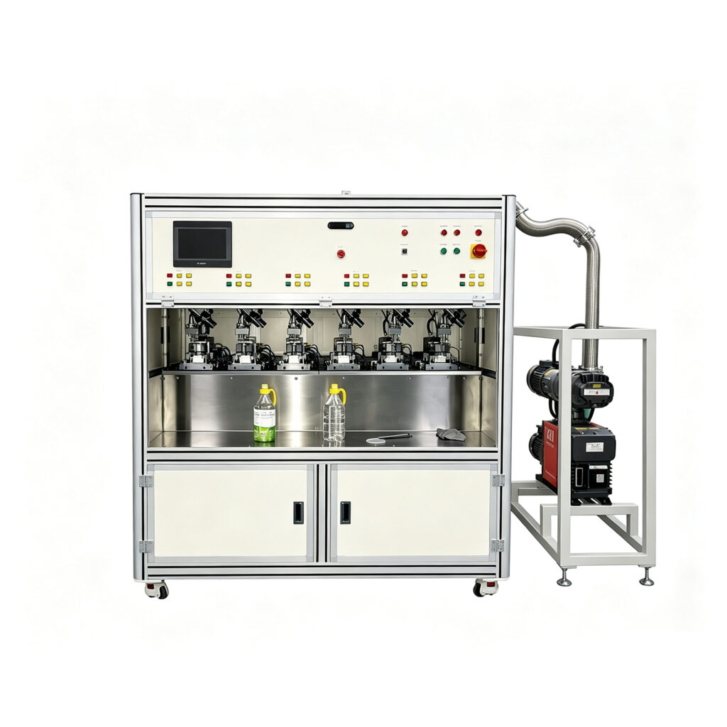
Vapor Chamber Degassing Machine for Reliable Production

Vapor Chamber Degassing Machine for Reliable Production 1. What Is a Vapor Chamber Degassing Machine? A Vapor Chamber Degassing Machine is specialized equipment used to remove unwanted gases from the internal cavity of a vapor chamber during manufacturing. It supports the vacuum-processing and sealing stages that help establish the conditions required for reliable heat transfer. A vapor chamber is a flat, sealed thermal component. It spreads heat through the evaporation and condensation of a working fluid, commonly water in electronics cooling applications. Inside the chamber, the working fluid absorbs heat and evaporates. The vapor travels toward cooler areas, releases heat through condensation, and returns through a capillary wick structure. However, non-condensable gases (NCGs), such as residual air, can interfere with vapor movement and condensation. Research on ultra-thin vapor chambers identifies residual NCGs as a concern for thermal performance, particularly in very thin designs. A vapor chamber degassing machine helps address this issue by evacuating the cavity through a designated port or an appropriate vacuum-processing arrangement. Depending on the equipment design, the system may combine several operations: Controlled vacuum evacuation Working-fluid management Pressure stabilization Degassing process control Filling-port sealing or welding Process monitoring and data recording Not every machine performs all these functions. Some systems focus on primary degassing, while others support secondary degassing or integrated vacuum filling and sealing. Therefore, manufacturers should choose a configuration that matches their vapor chamber design, required internal conditions, and production process. 2. Why Degassing Matters in Vapor Chamber Manufacturing 2.1 Removing Non-Condensable Gases Non-condensable gases do not condense in the same way as the working vapor under normal operating conditions. Their presence can interfere with heat transfer inside a vapor chamber. As a result, excessive residual gas may increase thermal resistance and reduce effective condensation area. A well-controlled degassing process helps reduce these unwanted gases. However, the final result also depends on cleaning, material preparation, fluid purity, internal structure, and sealing quality. 2.2 Supporting Thermal Performance Vapor chambers rely on a controlled internal environment to transport heat efficiently. If residual gas accumulates in critical areas, it can obstruct vapor flow and reduce effective heat-transfer performance. This issue becomes more important when a design has limited internal volume. Research into ultra-thin vapor chambers has investigated additional vacuuming and degassing steps to reduce residual NCGs and improve thermal behavior. Manufacturers should therefore establish vacuum-processing parameters through testing rather than applying the same settings to every chamber design. 2.3 Protecting Ultra-Thin Structures Ultra-thin vapor chambers have limited structural stiffness. Rapid pressure changes during evacuation can create unwanted mechanical stress. A suitable machine should support controlled evacuation and appropriate workpiece positioning. Depending on the design, engineers may need to validate pressure ramp-down, temperature, clamping, and cavity support. The goal is to remove unwanted gases without damaging the chamber walls or internal wick structure. 2.4 Improving Manufacturing Consistency Manual vacuum processing can introduce variation in connection quality, processing time, and operator decisions. An automated Vapor Chamber Degassing Machine can help standardize these conditions through programmed cycles and controlled process parameters. When the system also records relevant data, engineers can compare batches and investigate deviations more efficiently. 2.5 Supporting Reliable Final Sealing Degassing and sealing work together. The machine must maintain the intended internal conditions until the chamber is closed according to the approved process. If the sealing operation introduces contamination or allows air to re-enter, the benefits of evacuation may be reduced. For this reason, manufacturers should evaluate the vacuum system, port connection, sealing method, and leak-testing procedure as one coordinated process. 3. How a Vapor Chamber Degassing Machine Works The exact process depends on the chamber architecture, working fluid, and machine configuration. A typical production cycle includes the following stages. 3.1 Load and Position the Vapor Chamber The operator places the vapor chamber into a dedicated fixture. The fixture aligns the evacuation or filling port with the machine’s vacuum connection. Correct positioning helps prevent connection leakage and protects the thin chamber walls. The fixture should provide sufficient support without causing deformation. 3.2 Connect the Vacuum System The machine connects to the chamber through a designated port or another validated interface. The connection must remain stable throughout evacuation. Poor sealing at this point can introduce leakage and prevent the system from achieving the intended process conditions. 3.3 Start Controlled Evacuation The vacuum system removes gas from the internal cavity. Depending on the process, the machine may use a staged evacuation sequence rather than immediately applying maximum pumping capacity. Controlled evacuation can help manage pressure changes and reduce mechanical risks for sensitive structures. The required pressure profile depends on the chamber geometry, working fluid, temperature, and manufacturing specifications. 3.4 Manage the Working Fluid Many vapor chamber processes require degassing after working-fluid injection or as part of an integrated vacuum-and-filling cycle. This stage requires careful control because the working fluid can evaporate as the internal pressure decreases. The process must balance gas removal with fluid retention and distribution. The appropriate sequence varies by design. Manufacturers should confirm the validated procedure for their specific chamber rather than assuming that every machine uses the same workflow. 3.5 Stabilize the Vacuum Conditions The system may monitor pressure and time to determine whether the evacuation stage has reached its target conditions. Pressure stabilization can provide useful process information. However, a stable pressure reading alone does not prove that every non-condensable gas has been removed. Manufacturers should establish suitable verification criteria based on process trials and product requirements. 3.6 Seal the Chamber Once the required process conditions have been reached, the machine or a downstream station seals the relevant port. Depending on the design, the sealing method may involve resistance welding, laser welding, or another qualified joining process. The equipment configuration should prevent unnecessary exposure to air during the transition from evacuation to final closure. 3.7 Verify the Finished Product After sealing, manufacturers may perform leak testing, dimensional inspection, and thermal performance testing. These checks measure different characteristics. Leak testing assesses sealing integrity, while thermal testing evaluates the chamber’s heat-transfer behavior. A suitable quality plan

Vapor Chamber Degassing Machine for Reliable Production Read More »
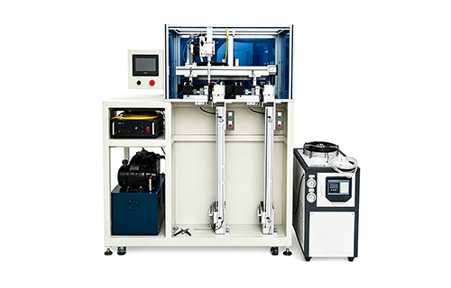
ultra thin vapor chamber laser sealing machine

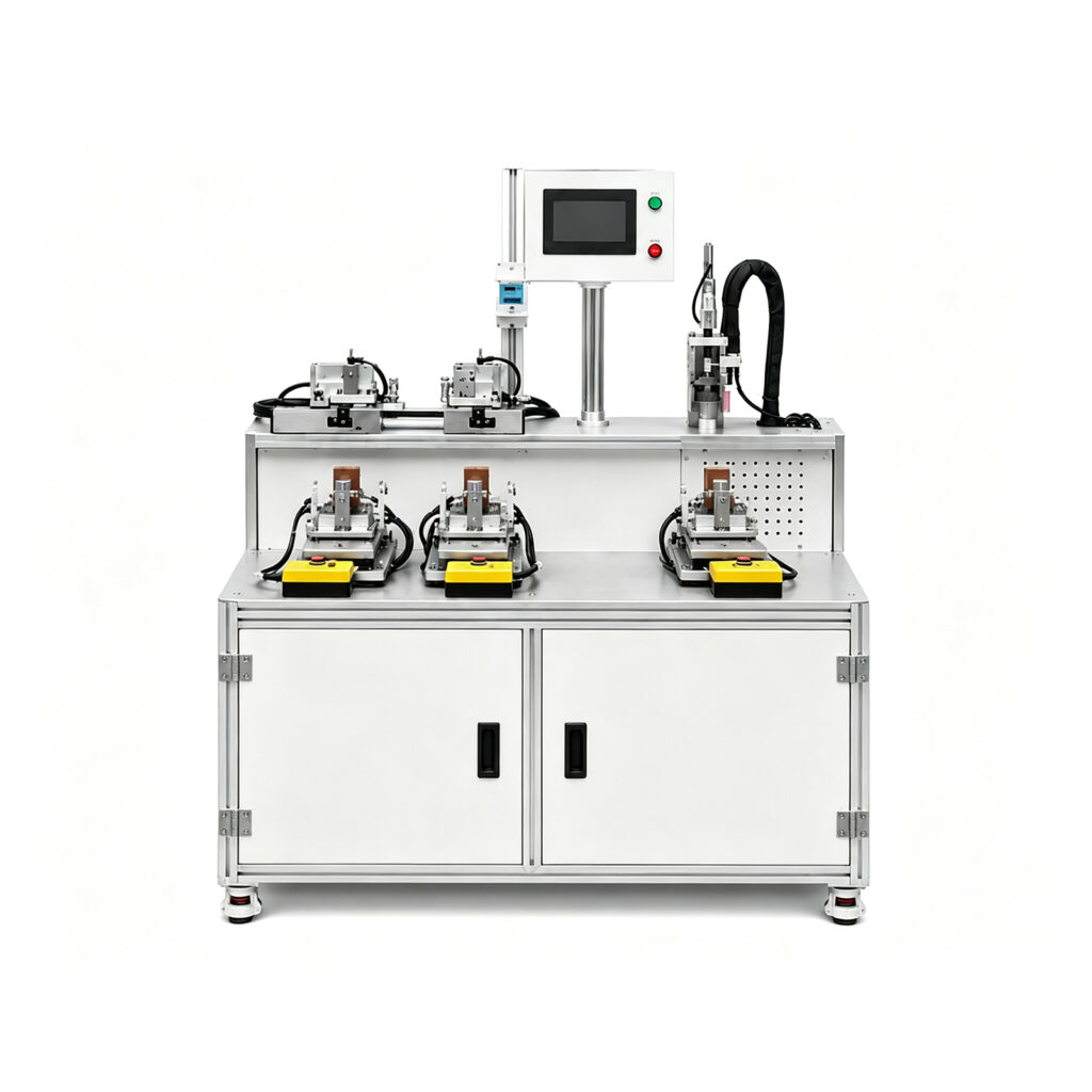
Resistance Welding Machine for Vapor Chamber Production

Resistance Welding Machine for Vapor Chamber Production 1. What Is a Resistance Welding Machine? A Resistance Welding Machine joins metal components by generating heat through electrical resistance while applying mechanical pressure. The equipment controls the welding current, welding time, and electrode force to create a joint between the workpieces. Unlike many arc welding processes, resistance welding typically does not require filler metal. Instead, electrical current generates localized heat at the joining interface. Pressure helps maintain contact and form the joint. Resistance welding includes several processes, such as spot welding, seam welding, projection welding, and butt welding. Each method serves different joint geometries and production requirements. For thermal management manufacturing, equipment selection depends on the component design. Vapor chambers and heat pipes often use thin copper or copper-alloy shells. These products require careful control of heat input and joint consistency. A resistance welding machine designed for suitable thermal components can support repeatable joining operations. For vapor chambers, continuous seam welding may be particularly relevant when the design requires a sealed perimeter. However, not every resistance welding machine suits every vapor chamber. Manufacturers must confirm the welding method, electrode arrangement, material compatibility, and sealing requirements before selecting equipment. 2. How Resistance Welding Works Resistance welding relies on electrical resistance to generate localized heat. The machine applies current through the workpieces while electrodes or other contact components maintain pressure. However, actual welding behavior also depends on contact resistance, material properties, electrode geometry, and heat transfer. 2.1 Workpiece Positioning First, the operator or automated handling system positions the metal components. The fixture keeps the joint aligned throughout the welding cycle. Accurate positioning helps maintain consistent contact conditions. It also reduces the risk of uneven welds caused by movement or misalignment. 2.2 Applying Electrode Force The machine applies pressure through the electrodes or welding mechanism. The force establishes electrical contact and helps control the joint during heating. Too little force may cause unstable contact, excessive local heating, or expulsion. Too much force may reduce interface resistance or deform thin components. Therefore, manufacturers should determine the appropriate force through process development and testing. 2.3 Applying Welding Current The power system supplies controlled current to the workpiece. Electrical resistance generates heat near the joint. The machine’s controller manages current duration and, depending on its configuration, other parameters such as current profile and pulse sequence. The goal is to create a suitable joint without excessive deformation or damage to surrounding material. 2.4 Holding and Cooling After the current stops, the machine may maintain force while the joint cools and solidifies. The exact sequence depends on the welding method and equipment design. Proper control helps produce repeatable results. Electrode condition and cooling also affect process stability during continuous production. 2.5 Inspecting the Joint After welding, manufacturers inspect the joint against established criteria. Inspection may include visual checks, dimensional measurements, destructive testing, or leak testing when the component requires a sealed cavity. For vapor chambers, the appropriate verification method depends on the sealing design and product specifications. 3. Why Resistance Welding Matters in Vapor Chamber Manufacturing 3.1 Supporting Thin Metal Components Vapor chambers use thin metal plates to create a compact sealed structure. Manufacturers must join these plates without introducing unacceptable deformation. A suitable resistance welding process can concentrate heat around the joining interface. Nevertheless, thin copper components can present challenges because copper conducts electricity and heat efficiently. The equipment and process must therefore match the material, thickness, joint geometry, and required weld characteristics. 3.2 Maintaining Sealing Integrity A vapor chamber relies on a sealed cavity containing a working fluid. The cavity supports evaporation and condensation, which move heat from one region to another. A defective perimeter joint may allow gas to enter or working fluid to escape. Such defects can affect product performance and reliability. For this reason, manufacturers must distinguish between a joint that provides mechanical attachment and one that meets the required sealing specification. Continuous resistance seam welding may suit certain vapor chamber designs because roller electrodes can create a continuous joint along a programmed path. Suitability depends on the actual chamber construction and validated process capability. 3.3 Improving Production Repeatability Manual joining operations can introduce variation in positioning, pressure, and heat input. Controlled welding equipment helps standardize these conditions. Manufacturers can establish qualified recipes for different product models. They can then monitor production and investigate deviations when defects occur. However, repeatability depends on more than the machine. Consistent incoming materials, clean surfaces, suitable fixtures, electrode maintenance, and operator training remain important. 3.4 Supporting Automated Manufacturing Resistance welding can integrate with fixtures, handling systems, and production controls. This makes it relevant to high-volume manufacturing where consistent cycle times matter. For thermal management products, the complete production process may include component preparation, internal structure assembly, welding, vacuum processing, filling, and testing. The welding machine should fit this broader workflow rather than operate as an isolated piece of equipment. 4. Main Types of Resistance Welding Different resistance welding methods address different joint requirements. Manufacturers should select the process according to the product’s structure and intended function. Welding type Working principle Typical application Spot welding Electrodes create localized weld points Sheet-metal assemblies and electrical components Seam welding Roller electrodes form a continuous or overlapping weld Suitable sealed or continuous sheet-metal joints Projection welding Designed projections concentrate current and force Components requiring one or multiple localized welds Butt welding Current and force join components at their ends Wires, rods, bars, and compatible end-to-end joints These processes share the principle of resistance heating, but their electrode designs and joint geometries differ. 4.1 Spot Welding Spot welding joins metal sheets at discrete locations. It suits applications where individual weld points provide sufficient mechanical strength. However, separate spot welds do not automatically create a continuous airtight perimeter. Manufacturers should not substitute spot welding for continuous sealing unless the product design specifically supports that approach. 4.2 Seam Welding Seam welding commonly uses rotating wheel electrodes to create a series of overlapping welds. With appropriate process settings, these welds can form a continuous seam. This

Resistance Welding Machine for Vapor Chamber Production Read More »

heatpipe vs vaporchamber contact us

VC Water Bath Bubble Leak Tester for Quality Control

VC Water Bath Bubble Leak Tester for Quality Control 1. What Is a VC Water Bath Bubble Leak Tester? A VC Water Bath Bubble Leak Tester is a quality inspection machine used to check the sealing integrity of vapor chambers and flat heat pipes. It helps manufacturers identify leakage points before defective products move to the next production stage. A vapor chamber transfers heat through the evaporation and condensation of a working fluid inside a sealed cavity. Its performance depends on several factors, including the internal structure, working fluid, vacuum conditions, and sealing quality. Therefore, manufacturers must verify that each chamber meets the required leak-tightness criteria. A water bath bubble leak tester uses a simple visual principle. The equipment introduces controlled pressure into a suitable test component and submerges it in water. If gas escapes through a defect, bubbles appear near the leakage point. This method offers two useful results: Leak detection: Operators can identify whether a tested component shows leakage under the selected test conditions. Leak localization: Visible bubbles can help operators locate the suspected defect for further investigation. Unlike methods that only measure pressure changes, water bath bubble testing can show the approximate location of a leak directly. However, detection sensitivity depends on the test pressure, observation time, defect characteristics, and operator judgment. For manufacturers, the VC Water Bath Bubble Leak Tester provides a practical option for production inspection, process troubleshooting, and weld quality verification. 2. Why Leak Testing Matters in Vapor Chamber Manufacturing 2.1 Protecting the Sealed Internal Environment Vapor chambers require a controlled internal environment to support phase-change heat transfer. Leakage can allow unwanted gas to enter or working fluid to escape. These changes may reduce thermal performance or affect long-term reliability. Consequently, manufacturers should verify sealing quality before releasing products. A leak test also helps engineers evaluate whether the selected joining process produces consistent results. 2.2 Identifying Defects After Welding Vapor chamber shells often contain thin metal plates. Their sealing edges must form a continuous joint without excessive deformation. Potential defects include: Incomplete welds Pinholes along the sealing seam Localized cracks Poor joint contact Defects caused by contamination Damage during subsequent handling A water bath bubble leak tester can help reveal certain defects that are difficult to identify through visual inspection alone. Nevertheless, bubble testing does not replace every inspection method. Manufacturers should select additional tests when their product specifications require greater sensitivity or quantitative leak-rate measurements. 2.3 Reducing Downstream Quality Risks Discovering a leak after final assembly can increase rework costs. It may also affect delivery schedules and customer confidence. Testing at an appropriate manufacturing stage helps detect defects earlier. In addition, the results can guide improvements to welding parameters, material preparation, and fixture design. For manufacturers building a complete production workflow, consider linking this section to the relevant Vapor Chamber Laser Welding Machine, Vapor Chamber Vacuum Filling & Welding Machine, and Vapor Chamber Production Line pages, if available on the website. 2.4 Supporting Traceable Quality Control A structured inspection process should record the product model, test conditions, inspection result, and any corrective action. These records help quality engineers compare production batches and investigate recurring problems. They also support internal audits and supplier quality management. The tester itself does not guarantee product reliability. Consistent results require validated procedures, trained operators, and appropriate acceptance criteria. 3. How a VC Water Bath Bubble Leak Tester Works The test process depends on the chamber design and machine configuration. A typical internal-pressurization method follows these steps. Step 1: Prepare the Vapor Chamber The operator checks the product model, external condition, and test requirements. The chamber should have completed the relevant manufacturing steps before inspection. The team must also confirm that the product can safely withstand the selected test pressure. Step 2: Connect the Test Fixture The operator installs the vapor chamber in a suitable fixture. The fixture provides the necessary connection for introducing test gas into the component. The connection must remain secure throughout the test. Otherwise, leakage at the fixture may produce misleading results. Step 3: Set the Test Parameters The operator selects the appropriate pressure and test duration. These settings should match the product specification. Thin-walled chambers may require particularly careful pressure control because excessive pressure can deform or damage the component. Never use a generic pressure setting for every product without engineering validation. Step 4: Introduce Controlled Pressure The equipment introduces air or another approved test gas into the chamber. The pressure creates a difference between the component’s interior and the surrounding water. If a through-leak exists, gas may escape through the defect. Step 5: Submerge the Component The operator places the pressurized component beneath the water surface. The water provides a visible medium for identifying escaping gas. A continuous stream of bubbles from a specific location may indicate a leak. Operators should distinguish actual leakage from bubbles trapped on the surface during immersion. Step 6: Observe and Record the Result The operator watches the component for the specified detection period. If bubbles emerge from a suspected defect, the operator records the location and follows the established rejection or rework procedure. If no bubbles appear, the component passes this particular test under the selected conditions. This result does not prove that every possible leak has been eliminated. Step 7: Release Pressure and Remove the Product After testing, the operator releases pressure safely before disconnecting the fixture. The component is removed and dried as required. Any product that fails inspection should follow the site’s documented nonconformance procedure. This workflow provides a practical way to combine leak detection with immediate defect localization. thermalmachinery.com 4. Key Features to Consider When Selecting the Equipment Not every bubble leak tester suits every vapor chamber. Buyers should evaluate the following features against their product requirements. Feature Importance for manufacturing Adjustable test pressure Helps accommodate different chamber designs and wall thicknesses Stable pressure regulation Supports consistent testing conditions Adjustable inflation time Allows controlled pressurization Adjustable detection time Provides sufficient observation time for the application Suitable fixture design Secures the product and

VC Water Bath Bubble Leak Tester for Quality Control Read More »

ultra thin vapor chamber laser sealing machine

Ultra-thin Vapor Chamber Laser Sealing Machine Guide

Ultra-thin Vapor Chamber Laser Sealing Machine Guide 1. What Is an Ultra-thin Vapor Chamber Laser Sealing Machine? An Ultra-thin Vapor Chamber Laser Sealing Machine is specialized equipment for joining the thin metal plates that form a vapor chamber. It uses a focused laser beam to create a continuous weld along the designed sealing path. Vapor chambers transfer heat through a phase-change process. Inside the sealed chamber, a working fluid evaporates near the heat source. The vapor then moves toward cooler regions and releases heat through condensation. A wick structure returns the liquid to the heated area. This process supports efficient heat spreading in compact electronic devices. However, the chamber must maintain a suitable internal environment to perform reliably. Manufacturers therefore need precise sealing technology. The equipment must join the metal plates without compromising the chamber’s geometry, wick structure, or sealing integrity. Ultra-thin designs make this requirement more demanding. Thin plates can deform under excessive heat or unsuitable clamping pressure. Even small defects may affect product quality. A properly configured laser sealing system helps manufacturers control several critical factors: Weld position and seam consistency Laser power and processing speed Heat input and thermal distortion Fixture alignment and workpiece stability Weld appearance and repeatability Compatibility with inspection and automation systems The machine’s configuration should match the product’s material, thickness, dimensions, and production requirements. Manufacturers should validate these factors through sample testing before full-scale production. 2. Why Laser Sealing Matters for Ultra-thin Vapor Chambers 2.1 Increasing Demand for Compact Thermal Solutions Electronic devices continue to combine higher computing performance with thinner product designs. Smartphones, tablets, gaming laptops, and other compact systems must manage concentrated heat within limited space. Ultra-thin vapor chambers help spread heat across a larger surface. This approach can improve temperature uniformity while preserving valuable internal space. However, thinner chambers create stricter manufacturing requirements. The sealing process must protect the thin shell while maintaining a continuous joint. Research published in Applied Thermal Engineering examined the performance and reliability of an ultra-thin vapor chamber with a thickness of 0.32 mm. The study highlighted the importance of vacuum processing and reliable sealing for thermal performance. 2.2 Controlling Heat Input Laser welding concentrates energy within a defined processing area. This localized heating can reduce unnecessary thermal exposure compared with less localized joining processes. Nevertheless, laser welding does not eliminate distortion automatically. Excessive power, poor fixturing, or an unsuitable welding path can still damage thin components. Manufacturers should optimize laser power, pulse settings where applicable, welding speed, focal position, and clamping conditions. These parameters work together to determine weld quality. 2.3 Maintaining Seal Integrity A vapor chamber relies on a sealed internal cavity. A defective weld may allow gas to enter or working fluid to escape. Such defects can affect the chamber’s ability to transfer heat. They can also reduce product reliability during service. A precision sealing process must therefore deliver both suitable weld strength and leak-tight performance. Visual inspection alone cannot confirm hermeticity. Manufacturers should select an appropriate leak-testing method and establish acceptance criteria for their specific product. 2.4 Supporting Consistent Production Manual welding can introduce variation between operators and production shifts. Automated laser systems can improve repeatability through programmed paths and controlled processing parameters. With suitable fixtures and monitoring, manufacturers can also reduce positioning errors and unnecessary rework. These benefits depend on proper machine setup, operator training, maintenance, and process validation. 3. How the Laser Sealing Process Works The exact workflow depends on the vapor chamber design and production strategy. A typical process includes the following stages. 3.1 Prepare the Metal Plates Manufacturers first prepare the upper and lower chamber plates. Depending on the design, these components may use copper or another suitable material. The preparation stage may include cutting, stamping, forming, cleaning, and dimensional inspection. Operators should check the sealing edges for contamination, burrs, and deformation. Clean and consistent joining surfaces help reduce weld defects. 3.2 Install the Wick Structure The wick structure supports liquid return inside the chamber. Its material and geometry depend on the required thermal performance and product design. Operators must position the wick correctly before closing the chamber. Incorrect placement may interfere with assembly or internal fluid circulation. The fixture should hold the plates securely without crushing the wick or changing the intended cavity geometry. 3.3 Align and Clamp the Workpiece The machine fixture positions the plates along the required sealing path. Accurate alignment helps maintain consistent seam placement. Clamping pressure also matters. Insufficient pressure may leave gaps between the plates. Excessive pressure may deform the thin shell. Manufacturers should develop a fixture design that balances stability, accessibility, and dimensional protection. 3.4 Perform Laser Sealing The laser follows a programmed path around the designated joint. The process melts the joining material locally and forms a continuous weld after solidification. The appropriate settings depend on material type, plate thickness, joint design, and required production speed. A stable process should avoid incomplete fusion, excessive penetration, burn-through, and unnecessary distortion. Manufacturers should establish validated parameter windows rather than relying on one setting for every product. 3.5 Inspect the Weld After welding, operators or automated systems inspect the seam. Common checks include weld continuity, surface appearance, positioning, and visible defects. Dimensional inspection can identify deformation around the sealing edge. Leak testing can then verify whether the finished chamber meets its specified sealing requirements. 3.6 Complete Vacuum Processing and Filling Laser sealing and final chamber closure are not always the same operation. Some designs require additional evacuation, working-fluid filling, or sealing of a dedicated filling port. The correct sequence depends on the chamber architecture and manufacturing method. Manufacturers should confirm whether the equipment performs perimeter sealing, filling-port sealing, or both. For broader process coordination, link this page to the relevant 🔗 Vapor Chamber Vacuum Filling & Welding Machine product page, if available. 4. Key Features of a Precision Laser Sealing Machine When evaluating an Ultra-thin Vapor Chamber Laser Sealing Machine, manufacturers should consider the following features. Feature Why it matters Adjustable laser parameters Supports process development for different materials and thicknesses Precision

Ultra-thin Vapor Chamber Laser Sealing Machine Guide Read More »

ultra thin vapor chamber laser sealing machine

Vapor Chamber Vacuum Filling & Welding Machine Guide

Vapor Chamber Vacuum Filling & Welding Machine Guide Introduction Modern electronics need reliable thermal management to maintain performance and operating stability. Therefore, manufacturers increasingly use vapor chambers to spread heat across compact surfaces. However, a vapor chamber requires more than a copper enclosure and an internal wick structure. Manufacturers must also control evacuation, working fluid charging, and final sealing. A Vapor Chamber Vacuum Filling & Welding Machine combines essential operations for preparing and sealing vapor chambers. Depending on its configuration, the system can evacuate internal air, introduce a measured amount of working fluid, and close the filling port. These operations directly influence chamber integrity and thermal performance. For example, residual non-condensable gases can interfere with vapor movement and reduce heat transfer efficiency. Meanwhile, inaccurate fluid charging can affect startup behavior and thermal resistance. An unreliable final weld can also cause leakage during service. Therefore, manufacturers need stable process control and suitable inspection procedures. Automation can improve repeatability while reducing manual handling during critical production stages. linkthermal focuses on thermal management manufacturing equipment and production solutions. Its website, https://linkthermal.com/, provides a starting point for exploring vapor chamber and heat pipe manufacturing equipment. This guide explains vacuum filling, laser welding, equipment configuration, quality control, and machine selection. It also outlines how manufacturers can integrate these processes into a complete production line. 1. What Is a Vapor Chamber Vacuum Filling & Welding Machine? A Vapor Chamber Vacuum Filling & Welding Machine combines vacuum processing, working fluid charging, and sealing operations. Depending on the design, one system can manage several steps within a coordinated production cycle. First, the machine removes air and non-condensable gases from the chamber. Next, its filling unit introduces a controlled quantity of working fluid. Finally, a suitable sealing mechanism closes the filling port. Some configurations use laser welding. Others use resistance welding, mechanical crimping, or alternative sealing technologies. The correct method depends on the chamber design and material. A typical system may include: Vacuum pumps and vacuum control valves A working fluid storage and delivery unit Precision metering equipment Product positioning fixtures A filling interface A pre-sealing mechanism A laser or resistance welding unit A programmable logic controller (PLC) A human-machine interface (HMI) Safety protection and process monitoring Moreover, some machines record vacuum levels, filling quantities, and welding parameters. This information helps manufacturers track production quality and investigate process deviations. For example, an integrated machine can reduce transfers between separate vacuum, filling, and sealing stations. However, actual cycle time and accuracy depend on the selected configuration and product requirements. thermalmachinery.com 2. Why Vacuum Filling and Welding Matter A vapor chamber transfers heat through evaporation and condensation inside a sealed enclosure. Its internal wick returns condensed liquid toward the heat source. Therefore, manufacturers must maintain suitable internal conditions throughout the product’s service life. 2.1 Removing Non-Condensable Gases Residual air and other non-condensable gases can interfere with vapor movement. They may also reduce the effective heat transfer area. Vacuum processing helps remove these unwanted gases before final sealing. Consequently, effective degassing supports stable thermal performance. 2.2 Controlling Working Fluid Quantity Every vapor chamber design requires a suitable working fluid charge. Too little fluid may restrict liquid return and impair heat transfer. Conversely, excessive fluid can reduce available vapor space and affect operating behavior. Therefore, manufacturers should determine the target charge through product design and process validation. 2.3 Maintaining Hermetic Sealing The finished chamber must retain its working fluid and internal conditions. Even a small leak can compromise reliability. Therefore, manufacturers should validate the filling-port seal and inspect finished products using suitable leak testing. 2.4 Supporting Production Consistency Manual filling can introduce variation between batches. Automated metering and programmable process settings help reduce that variation. Moreover, integrated processing can reduce handling between stations. This arrangement also simplifies process coordination. 3. How the Machine Works The machine follows a controlled sequence that connects evacuation, fluid charging, and sealing. First, operators load the prepared vapor chamber into a dedicated fixture. The fixture aligns the filling port with the processing head. Next, the machine establishes a suitable connection around the port. Its vacuum system then removes air and residual gases according to the validated process recipe. After reaching the required vacuum condition, the filling unit delivers the specified working fluid quantity. Depending on the design, the system may use a metering pump, flow measurement, or weighing feedback. The machine then closes the filling port temporarily or prepares it for immediate sealing. This step helps limit air ingress and fluid loss. Finally, the sealing unit completes the closure. The machine may use laser welding, resistance welding, or another suitable method. After sealing, operators or automated inspection equipment verify the product against defined acceptance criteria. The exact sequence varies by equipment design. Some systems use a dedicated filling tube, while others use specialized port arrangements. Consequently, buyers should confirm compatibility with their vapor chamber construction before selecting equipment. 4. Main Components of the Equipment 4.1 Vacuum System The vacuum system removes air and non-condensable gases from the chamber. Depending on the required vacuum level, the configuration may combine roughing pumps, high-vacuum pumps, valves, and pressure sensors. Furthermore, vacuum stability matters as much as pump capacity. Manufacturers should select the system according to internal volume, leakage characteristics, and cycle time. 4.2 Precision Filling Unit The filling unit delivers the specified working fluid quantity. Depending on the design, it may use a metering pump, flowmeter, weighing system, or combined feedback controls. Moreover, the fluid path should support cleanliness and compatibility with the selected working fluid. 4.3 Positioning Fixture The fixture holds the vapor chamber and aligns the filling port. Accurate positioning helps prevent connection problems and inconsistent sealing. Additionally, quick-change fixtures can simplify production changes between compatible product sizes. 4.4 Welding and Sealing Unit The sealing unit closes the filling port after fluid charging. Laser welding offers localized energy delivery and programmable motion. Resistance welding provides another option for suitable joint designs. However, manufacturers must validate each method against material thickness, port geometry, and sealing requirements. 4.5 Control and

Vapor Chamber Vacuum Filling & Welding Machine Guide Read More »

heatpipe vs vaporchamber contact us

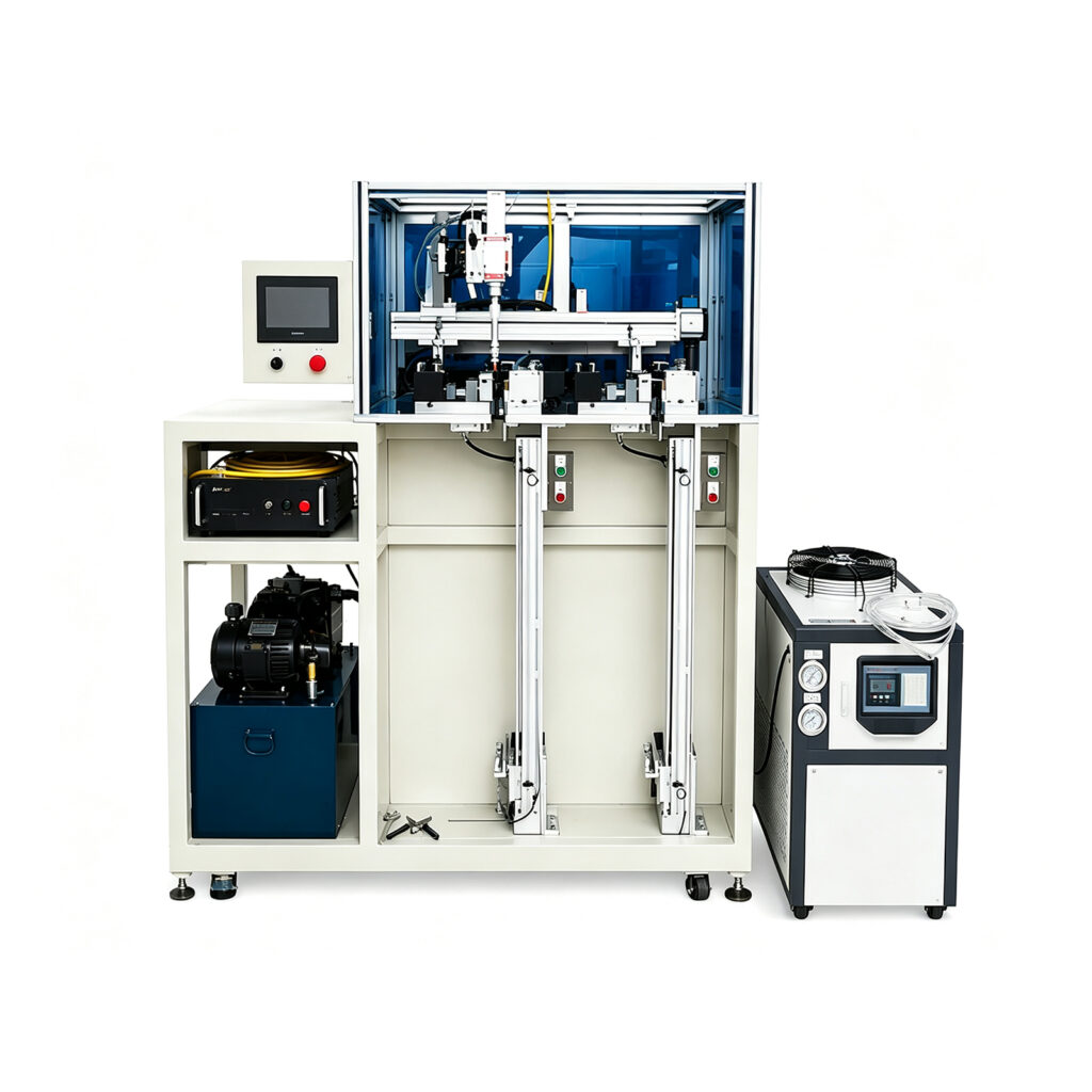
Laser Welding Machine for Vapor Chamber: Complete Guide

Laser Welding Machine for Vapor Chamber: Complete Guide Introduction A Laser Welding Machine for Vapor Chamber plays an important role in modern thermal management manufacturing. As electronic devices become more powerful, cooling components must handle higher heat loads within smaller spaces. Therefore, manufacturers need precise and reliable joining technologies. Vapor chambers use evaporation and condensation to spread heat across their surfaces. However, their performance depends on a clean internal environment and reliable sealing. Even a small welding defect can compromise chamber integrity. Consequently, manufacturers must control the welding process carefully. Laser welding offers concentrated heat input, programmable motion, and precise joint control. Moreover, automation can improve production consistency and reduce repetitive manual operations. Copper vapor chambers present additional manufacturing challenges. Their high thermal conductivity and laser reflectivity require suitable equipment and carefully selected welding parameters. For manufacturers, choosing the right laser welding system means balancing weld quality, production capacity, automation, and long-term operating costs. linkthermal focuses on thermal management manufacturing equipment, including vapor chamber and heat pipe production solutions. This guide explains how laser welding works, which factors affect sealing quality, and how manufacturers can select suitable equipment. 1. What Is a Laser Welding Machine for Vapor Chamber? A Laser Welding Machine for Vapor Chamber uses concentrated laser energy to join copper components during vapor chamber manufacturing. The equipment creates localized heat at the joining area. As a result, manufacturers can produce narrow weld seams while limiting unnecessary heating around the joint. Unlike conventional welding methods, laser welding does not require direct contact between the energy source and the workpiece. Therefore, manufacturers can integrate the process with automated positioning and motion systems. A typical machine may include: Fiber laser source or another suitable laser system Precision laser welding head Automatic positioning system Servo-controlled motion platform Workpiece clamping fixtures PLC or industrial control system Cooling equipment Protective enclosure and safety interlocks Optional vision and weld monitoring systems Additionally, manufacturers can configure the equipment for different vapor chamber sizes and sealing requirements. For example, some machines weld the perimeter of copper enclosures. Others support final sealing of filling or evacuation ports. Although both processes use laser technology, they require different tooling and welding parameters. Therefore, manufacturers should identify the intended welding operation before selecting equipment. 2. Why Vapor Chambers Require Precision Laser Welding Vapor chambers operate through a continuous two-phase heat transfer cycle. Inside the sealed enclosure, working fluid absorbs heat and evaporates. The vapor then travels toward cooler regions and releases heat through condensation. Meanwhile, the internal wick returns condensed liquid toward the heat source. This cycle requires a controlled internal environment. However, poor welding can introduce leakage paths. Consequently, air may enter the chamber, or working fluid may escape. Both problems can reduce thermal performance and product reliability. Reliable Hermetic Sealing A vapor chamber requires joints that maintain the specified internal conditions. Therefore, manufacturers must control weld continuity, penetration, and potential leakage. Limited Thermal Distortion Thin copper chambers can deform during excessive heating. Laser welding concentrates energy near the joint. Consequently, suitable process settings can reduce unwanted thermal distortion. Consistent Product Dimensions Vapor chambers often fit inside compact electronic assemblies. Therefore, welding must preserve the required dimensions and flatness. Compatibility With Automation High-volume production requires repeatable manufacturing processes. Moreover, automated laser welding systems can follow programmed paths and maintain consistent operating sequences. However, reliable results still depend on suitable fixtures and validated process parameters. 3. How Does Vapor Chamber Laser Welding Work? Laser welding uses concentrated optical energy to melt and join metal surfaces. First, operators prepare the copper components and inspect their joining surfaces. Next, the positioning system places the workpiece inside the welding station. Precision fixtures then secure the components. Afterward, the laser source generates a beam and directs it toward the joint. The copper absorbs part of the laser energy and develops a localized molten region. Meanwhile, the motion system moves the beam or workpiece along the programmed path. As the molten metal cools, it forms a continuous weld. Finally, inspection equipment evaluates the resulting joint. Laser Energy and Copper Copper presents special challenges because it conducts heat rapidly. Additionally, copper reflects a significant portion of certain laser wavelengths. Therefore, laser wavelength, power, beam characteristics, and surface condition influence welding stability. Welding Modes Manufacturers may use conduction welding or keyhole welding. Conduction welding generally creates shallower joints through surface heating. Meanwhile, keyhole welding can produce deeper penetration under suitable conditions. However, excessive penetration can damage thin chamber walls. Therefore, manufacturers must select the welding mode according to joint geometry and material thickness. 4. Main Components of a Laser Welding Machine 4.1 Laser Source The laser source generates the energy required for welding. Fiber lasers commonly support industrial metal joining applications. However, manufacturers should evaluate wavelength, beam quality, and operating characteristics for copper processing. 4.2 Laser Welding Head The welding head directs and focuses laser energy onto the workpiece. Moreover, suitable optical components help maintain consistent beam delivery. 4.3 Precision Motion System Servo motors and linear guides control welding movement. Consequently, the machine can follow programmed welding paths. 4.4 Workpiece Fixtures Fixtures maintain component alignment during welding. Additionally, suitable clamping helps control joint gaps and movement. 4.5 Control System The controller coordinates laser output, motion, and machine sequences. Operators can adjust welding parameters according to validated process recipes. 4.6 Cooling System Laser equipment generates heat during operation. Therefore, suitable cooling systems help maintain stable equipment temperatures. 4.7 Safety Protection Laser welding presents optical, electrical, and fume-related hazards. Consequently, industrial systems require appropriate enclosures, interlocks, extraction, and emergency controls. 5. Step-by-Step Vapor Chamber Laser Welding Process A reliable welding process starts before the laser turns on. Step 1: Copper Surface Preparation First, manufacturers clean the joining surfaces. Oil, oxidation, and particles can affect laser absorption and weld stability. Therefore, consistent cleaning supports reliable processing. Step 2: Component Positioning Next, operators or automated systems position the vapor chamber components. Precision fixtures maintain the required alignment. Step 3: Parameter Selection Manufacturers select suitable laser power, welding speed, focus position, and shielding conditions.

Laser Welding Machine for Vapor Chamber: Complete Guide Read More »

ultra thin vapor chamber laser sealing machine

Conveyor Automatic Sand Blasting Machine Guide

Conveyor Automatic Sand Blasting Machine Guide   Introduction Manufacturers must use reliable equipment for the cleaning of components prior to the application of paint or other types of processing. The success of metal surface preparation will affect how well the coating adheres to the metal, how good the final product looks, and its ability to resist corrosion. A conveyor automatic sand blasting machine uses both automated material movement and abrasive blasting technologies. This machine moves work pieces through a blasting chamber to remove rust, mill scale, and other surface contamination. Conveyor machines are designed for continuous production. Therefore, factories using this type of machine can produce at higher volumes while reducing the need for manual handling and maintaining a steady operating environment. The choice of the appropriate equipment depends on several factors besides just comparing the amount of blasting power. The size of the workpiece, what type of abrasive is selected, how fast the conveyor can move and the requirements for the finished surface will affect the overall performance. The manufacturer needs to take into account the effects of abrasive recovery, dust collection, maintenance, and workplace safety on the cost of operation for the business in the long-term, and on how effectively the business operates. The following guide describes how a conveyor blasting machine functions, where the manufacturing industry uses them, and how potential users may determine what type of configuration is right for their needs. This course covers many aspects of production planning, including but not limited to, the practicalities involved with creating a production schedule; cost of operating machinery; and how to maintain your equipment. 1. What Is a Conveyor Automatic Sand Blasting Machine? A Conveyor Automatic Sand Blasting Machine moves workpieces into a sealed chamber where it applies abrasive media to the surface of the workpieces. The conveyor controls how workpieces move and the blasting units direct the abrasive particles at the target surfaces. Therefore, the machine will remove rust, scale and any other unwanted materials. Industrial manufacturers generally use the phrase sand blasting when referring to their processes. However, most industrial manufacturers typically utilize a wide range of abrasive materials for cleaning and preparation purposes. Some examples of these materials include steel shot, steel grit, aluminum oxide, and other appropriate non-metallic abrasives. The right type of abrasive for a job depends on the type of material being worked with and how smooth the final finish needs to be. A typical conveyor blasting machine includes: An automatic conveyor system An enclosed blasting chamber Blast wheels or compressed-air nozzles An abrasive recovery system An abrasive separation unit An industrial dust collector An electrical control system Safety guards and interlocks In addition to selecting various types of conveyors depending on what they are manufacturing, manufacturers may also choose from several conveyor options based on their manufacturing process needs. Roller conveyors can be used to transport most types of steel plate as well as some structural components. Mesh belts on the other hand can be used to move small parts that are of an appropriate size for this type of conveyor. As a result of this, when selecting equipment, it is best to start by considering the types of work pieces you will be processing instead of using general information about what machines can do. 2.How Does a Conveyor Sand Blasting Machine Work? A conveyor blasting machine integrates material handling, abrasive acceleration, cleaning of surfaces and recovery of media. First, operators load the workpieces on to the conveyor. The conveyor will transport each piece toward the blasting area. The chamber is equipped with compressed air nozzles or blast wheels that will use force to cause abrasive particles to strike the surface of the work piece repeatedly. As the particles hit the surface over and over again, they begin to break away the undesirable material on the top layer of the work piece. The conveyor is running at a specific rate which controls the amount of time that every part will stay in the blast chamber. After blasting, the conveyor takes the treated components to the discharge zone. There are a variety of ways to clean off remaining abrasive material such as air knives, brushes, etc. At the same time, the recovery system will also collect reusable media. A separator(s) will be used to remove any dust and/or unsuitable particles prior to the media being recirculated. At the end of the process, workers review the surface prior to painting, coating, welding, or assembly. Important Operating Parameters Several factors determine the final surface quality. Conveyor speed: Controls exposure time inside the blasting chamber. Abrasive type: Influences cleaning action and surface profile. Blasting intensity: Determines the impact applied to the workpiece. Abrasive flow: Affects coverage and material removal. Workpiece orientation: Influences access to different surfaces. Dust Removal: To remove dust particles from the air, and to provide the proper environment for operation. As such, manufacturers need to find a balance between both variables. If only one variable is changed, i.e., the intensity of the blast is increased, it could lead to surface damage or increased consumption of abrasives. 3.Main Components of the Machine 3.1 Conveyor System The conveyor system moves work pieces through the blasting chamber at a pre-determined rate. The manufacturer has several options for conveyor systems: roller conveyors, mesh belts, rubber belts and/or custom fixtures. As an example of this type of application, roller conveyors provide support for numerous large steel plates and other manufactured assemblies. On the other hand, mesh belts are designed to handle smaller parts that fit well within their design parameters. However, the conveyor must be able to hold up the weight of the workpiece and keep it in a position that is secure. 3.2 Abrasive Blasting System The blasting system accelerates abrasive media toward the workpiece. High volume production processes are suitable for turbine blast wheel systems, whereas compressed air blasting systems provide flexibility in processing some types of shapes and/or processing specifications. Moreover, the amount of blast machines and their positioning will decide how much

Conveyor Automatic Sand Blasting Machine Guide Read More »

vapor chamber degassing machine

Vacuum Sintering Furnace: Process, Uses & Selection Guide

Vacuum Sintering Furnace: Process, Uses & Selection Guide Focus Keyphrase: Vacuum Sintering Furnace SEO Title: Vacuum Sintering Furnace: Process, Uses & Selection Guide Meta Description: Learn how a vacuum sintering furnace works, its applications, key features, and selection tips for vapor chamber and heat pipe production. Introduction A Vacuum Sintering Furnace creates a controlled environment for bonding metal powders and processing porous materials. In thermal management manufacturing, this equipment has a particularly important role. For example, copper powder can form a porous wick structure inside a heat pipe or vapor chamber. That structure controls how liquid moves during the heat transfer cycle. As a result, the sintering process can directly influence the final thermal performance. However, good sintering requires more than simply heating metal powder. Temperature, vacuum level, heating speed, holding time, powder characteristics, and cooling conditions all matter. A suitable furnace brings these variables together in one controlled process. For manufacturers, that means better repeatability and easier process management. linkthermal focuses on thermal management manufacturing equipment for vapor chambers, heat pipes, and related cooling components. Its equipment portfolio covers processes such as powder filling, sintering, vacuum treatment, sealing, and thermal testing. You can learn more about its thermal manufacturing solutions through the official linkthermal website. 1. What Is a Vacuum Sintering Furnace? A Vacuum Sintering Furnace heats materials under a controlled vacuum environment. The process allows metal particles to bond without fully melting the main material. During heating, atoms move across the contact areas between particles. This diffusion gradually strengthens the structure. At the same time, the original powder arrangement develops interconnected pores. That feature makes sintering especially useful for porous copper wick structures. A typical vacuum sintering furnace includes a heating chamber, insulation, vacuum system, temperature sensors, and control system. Depending on the process, the furnace can also include controlled gas introduction and cooling functions. The exact configuration depends on the material and application. For instance, a copper wick for a vapor chamber may require different process conditions from another powder metallurgy component. Therefore, manufacturers should select the furnace around the actual product process. 2. How Does a Vacuum Sintering Furnace Work? The basic process looks straightforward. However, each stage requires careful control. First, the operator loads the prepared workpieces into the furnace chamber. The vacuum system then removes air and other gases from the chamber. After reaching the required pressure, the heating system starts the programmed cycle. The furnace gradually raises the temperature according to the selected profile. During this stage, the powder particles begin to bond at their contact points. The furnace then maintains the target temperature for a defined period. This holding stage allows diffusion to develop the required structure. After sintering, the system follows a controlled cooling cycle. Finally, the operator removes the components after reaching suitable handling conditions. The process may also include gas backfilling during cooling. This option depends on the furnace design and material requirements. The important point is consistency. A stable process helps manufacturers produce wick structures with similar properties from batch to batch. 3. Why Is Vacuum Sintering Important for Thermal Components? Heat pipes and vapor chambers depend heavily on their internal wick structures. The wick moves condensed working fluid back toward the heat source. Therefore, its pore structure affects capillary pressure and liquid permeability. A poorly controlled sintering process can change those properties. For example, excessive sintering can reduce the available pore volume. That change may restrict liquid movement. On the other hand, insufficient bonding can produce a weak wick structure. The powder may also lose its intended geometry during later processing. Therefore, manufacturers need a controlled sintering process. A Vacuum Sintering Furnace provides precise control over the thermal environment. It also reduces exposure to unwanted atmospheric gases. However, vacuum does not automatically solve every oxidation problem. Copper powder characteristics and surface condition remain important. In some processes, manufacturers may also consider a controlled inert or reducing atmosphere. The right choice depends on the material and required wick properties. 4. Vacuum Sintering Process A typical process contains several stages. 4.1 Powder Preparation The process starts with suitable metal powder. For copper wick manufacturing, particle size distribution matters. Powder shape and surface condition also influence the final pore structure. Therefore, manufacturers should control powder quality before loading the furnace. 4.2 Powder Filling The prepared powder enters the component or a dedicated sintering fixture. For vapor chambers, a 🔗 Vapor Chamber Powder Filling Machine can help control powder placement. For heat pipes, a 🔗 Heat Pipe Powder Filling Machine can provide a similar function. Accurate filling creates a more consistent starting structure. 4.3 Loading Operators place the prepared components into suitable fixtures. The fixture should maintain the required geometry during heating. It should also tolerate the selected temperature and atmosphere. 4.4 Vacuum Pumping The chamber closes before the vacuum system starts. The pumps remove air from the working area. The required vacuum level depends on the material and process. Therefore, manufacturers should not select a pump based on vacuum level alone. Pumping speed and chamber volume also matter. 4.5 Heating The furnace gradually increases the temperature. A controlled ramp helps reduce unnecessary thermal stress. The heating profile depends on the powder and target structure. 4.6 Sintering The furnace reaches the selected sintering temperature. The powder particles then develop stronger connections through diffusion. The holding period determines how far this process progresses. Consequently, temperature and time require careful optimization. 4.7 Cooling The furnace cools the components under controlled conditions. The cooling method depends on material requirements and furnace design. Rapid cooling may create unwanted thermal stress in some applications. 4.8 Inspection After cooling, manufacturers inspect the finished wick or component. They may check dimensions, surface condition, porosity, and structural strength. For thermal components, further capillary and thermal tests may also be necessary. 5. Vacuum Sintering for Vapor Chamber Wick Structures Vapor chambers use a sealed internal cavity to transfer heat. Inside that cavity, the wick helps circulate the working fluid. Copper powder sintering offers one practical method for creating this wick. The powder fills the required region before

Vacuum Sintering Furnace: Process, Uses & Selection Guide Read More »

vapor chamber vacuum filling & welding machine

Vapor Chamber Hot Press Hydraulic Machine Guide

Vapor Chamber Hot Press Hydraulic Machine Guide Intro This Vapor Chamber Hot Press Hydraulic Machine allows precision forming, flattening, and heat treating for vapor chamber production. Vapor chambers are becoming more common as electronic devices continue to produce more heat. Manufacturers require thermal management components they can trust to do the job. Vapor chambers allow for spreading of heat with evaporation and condensation methods. Additionally, vapor chambers are typically smaller form factors which allow for more dense high-performance cooling implementations. Tighter tolerances on dimensions and consistent processing parameters are required to produce reliable vapor chambers. A Vapor Chamber Hot Press Hydraulic Machine unites pressurization, heating, and precision positioning. As a result, manufacturers are able to execute appropriate forming and thermal pressing. The process allows for better repeatability when producing vapor chambers. Automation of the control system can allow for more stability in temperature, pressure, and processing times. linkthermal specializes in thermal management manufacturing equipment and production applications. The company offers equipment to produce vapor chambers, heat pipes, as well as other thermal processing equipment. linkthermal also offers customization to the equipment configuration based on product sizes, production specifications, and automation needs. Visit linkthermal to see what solutions they offer. 1. What Is a Vapor Chamber Hot Press Hydraulic Machine? A Vapor Chamber Hot Press Hydraulic Machine accurately controls hydraulic force while heating components of vapor chambers. Ideal equipment supports vapor chamber production processes which require simultaneous pressure and heat. As the name suggests, a hot press forces together two surfaces with heat, while a regular cold press applies pressure without heat. With heat integrated into the pressing mechanism, manufacturers can complete various thermal forming/flattening processes and bonding operations. Keep in mind that the exact function of the hot press depends on the vapor chamber build and production process design. Key components of a hydraulic hot press include: – Pressing force provided by hydraulic pressure – Heated pressing surfaces – Controlled temperature regulation – Programmable pressure settings – Adjustable pressure hold time – Work positioning fixtures – PLC controller – Safety mechanisms and protection Automatic feeding/unloading systems are also an option for manufacturers. As a result, vapor chamber hot press machines can be used alone or integrated into a production line. 2. How Does a Vapor Chamber Hot Press Hydraulic Machine Work? Hydraulic hot presses utilize force and precise heating to complete production processes. Operators input the necessary processing parameters into the controller. Next, the heating system begins to raise the temperature of the pressing surfaces. The material or vapor chamber components are placed into the fixture. The hydraulic system presses the material with the set amount of pressure. Simultaneously, the temperature is regulated to stay within the desired threshold. The system holds the pressure and temperature for the required amount of time. Pressure is released by the hydraulic system so the material can be removed. Summary of the Main Working Principles Fluid supplied to the cylinder from a pump creates hydraulic pressure. The press’s mechanical components create force. Heating elements warm the heating plates. Temperature sensors detect the temperature of the plates. The hydraulic pump and valves control the pressure applied to the workpiece. Automatic controls allow for programmable and repeatable processes. A programmable logic controller ensures all components work together to complete the process. Operators can store recipes for various materials. 3. Main Components of the Equipment Essentially, a hydraulic hot press is a collection of mechanical, hydraulic, electronic, and thermal technologies. 3.1 Hydraulic Power Supply This system pressurizes hydraulic fluid to create force. A hydraulic hot press hydraulic system typically includes a pump, cylinders, valves, and hydraulic hoses. Pressure regulation is also an important component to keeping a consistent operation. 3.2 Heating Plates Heat is applied to the workpiece with heated plates. Flatness and heat distribution will affect your process. Workpiece size determines plate size. 3.3 Temperature Controls Temperature sensors are used to measure the temperature of the heating plates. The controller uses input from these sensors to turn the heating elements on and off to achieve desired temperature. 3.4 Work Holding Fixtures Components of the vapor chamber are held in place with fixtures. The fixture is also important to ensure the workpiece does not move or shift during your process. 3.5 Controller A controller ties all of these components together. A PLC controls the movement of the hydraulic system, temperature, pressure hold times, and safety interlocks. Operators can input their process parameters using an HMI or human-machine interface. 3.6 Machine Structure Without a strong metal frame, the machine will not be able to withstand the hydraulic pressure. 3.7 Cooling System If your process involves controlled cooling, your system will need a way to cool the workpiece. This all depends on what your process is. 3.8 Safety System Just because your system is programmable does not mean you can forgo any safety mechanisms. Hydraulic systems deal with tons of pressure, so there will always be a need for proper guarding, interlocks, E-stops, and overpressure valves. 4. Vapor Chamber Hot Press Manufacturing Process Temperature, force, and time must be closely monitored during the hot pressing process. Step 1: Load Material Load and inspect vapor chamber material to ensure proper dimensions and surface quality. Clean the material if necessary. Step 2: Prepare Machine Inspect hydraulic systems and heated pressing surfaces. Configure machine with proper pressure, temperature, and hold time parameters. Ensure fixture is properly aligned. Step 3: Adjust Temperature Preheat the plates to your desired temperature. Watch the temperature gauge to make sure the temperature stays consistent. Step 4: Position Workpiece Load vapor chamber into the fixture. Ensure workpiece is situated correctly. Step 5: Hydraulic Pressing Begin press and close lid. The hydraulic system will pump fluid into the cylinder to create enough force to complete the process. Step 6: Pressure Hold Machine will hold pressure for set period of time. Step 7: Release Pressure System will bring pressure back down to zero and open the lid. Step 8: Inspect Finished Product Inspect vapor chamber for quality. Test for flatness, thickness, dimensions, and

Vapor Chamber Hot Press Hydraulic Machine Guide Read More »

vapor chamber vacuum filling & welding machine

Vapor Chamber Fully automatic laser sealing machine

0Introduction Introducing the Vapor Chamber Fully automatic laser sealing machine, your solution for precision and efficiency in advanced thermal management manufacturing. With increasing power density in electronic products, the thermal management issue encountered by manufacturers is becoming more and more severe. To solve vapor chamber production technology has become more and more important. Heat pipes generate heat by evaporation and release heat by condensation. The advantage of vapor chambers is also that their structure is relatively small. However, to manufacture vapor chambers, there will be welding points, sealing points to be considered, and stability of the production process. If there are tiny leaks during sealing, it may cause problems such as vacuum leakage and poor thermal conductivity. As a result, manufacturers are beginning to look for advanced sealing equipment. Fully automatic laser sealing is a sealing equipment that integrates precision laser welding, flexible positioning machine, intelligent parameter control system. In addition, you can help manufacturers increase production consistency and reduce hand-touch. This thermal management manufacturing equipment supplier introduces you to linkthermal. linkthermal specializes in the production of vapor chamber production equipment, heat pipe manufacturing systems, and various supporting thermal processing equipment. Plus, linkthermal can also guide you to choose equipment based on products and production processes, and the degree of intelligence needed. Please click linkthermal to learn about the available machines.     1. What Is Vapor Chamber Fully automatic laser sealing machine? A Vapor Chamber Fully automatic laser sealing machine applies laser energy to form sealed metal joints. The system facilitates sealing processes applied during vapor chamber production. Unlike traditional welding machinery, laser sealing equipment focuses energy to the area to be joined. As a result, users can produce small weld beads with reduced heat input. Additionally, automated movement maintains consistent welding trajectories. Many systems offer several capabilities, such as: Automatic loading Precise product positioning Lasers welding/sealing Programmable movements On-machine process monitoring Automatic product unload Recording production data Keep in mind that actual features vary based on the configured system. Users typically employ vapor chamber sealing machines when producing copper vapor chambers and other thermal components. Thermal vias can be welded during this process as well. Heat pipe manufacturing also benefits from the appropriate laser sealing solution. In summary, vapor chamber automatic laser sealing machines are vital to thermal processing. 2. How Does Automatic Laser Sealing Machine Work? Automatic laser welding joins metal parts using concentrated light energy. Here is a brief overview of the laser sealing process: Users enter the desired weld settings into the control interface. An automatic feeding mechanism transports the parts to the welding zone. Once in place, clamps hold the pieces at the correct location. The laser head traces the programmed welding path. The focused laser beam creates a small molten pool at the joint. The molten solder solidifies, creating a seal. The machine completes the welding cycle and moves the welded part towards exit. Main Working Principles Laser source The laser generator creates a focused beam of light. As a result, the laser applies concentrated thermal energy to a small area. Motion control Servo motors allow users to control the motion of either the welding head or workpiece. In some cases, fixtures provide additional support to ensure proper alignment. Welding control A control system monitors and adjusts welding speed, laser power, and machine movement. Thus, manufacturers can reproduce the same weld consistently over time. Quality assurance Visual inspection systems allow users to verify weld quality. Variables such as bead geometry and color may be assessed. However, technicians should also conduct leak tests to verify weld integrity. 3. What Are the Main Components of Fully Automatic Laser Sealing Machine? Fully automated laser welding machines use several technologies to produce welds. The following sections briefly describe the components of a laser sealing system. 3.1 Laser Welding Source Lasers produce the energy that melts metal parts together. When deciding on a laser source, material type and thickness play a significant role in the decision process. However, laser wavelength, power density, and beam quality also play a crucial role. 3.2 Precision Motion System Motion systems allow the movement of welding head or workpiece. Servo motors enable precise incremental motion on desired axes. Guideways provide precision and repeatability of motion. 3.3 Automatic Feeding System Material feeders bring parts to the welding station. As a result, operators can avoid time-consuming manual tasks. Automatic feeders also allow for synchronized production cycles. 3.4 Workpiece Positioning Fixtures Positioning fixtures hold the workpiece in place during the welding process. In many cases, fixtures prevent movement and displacement of the workpiece. The material and shape of fixtures can affect thermal conductivity during welding. 3.5 Laser Welding Head The welding head allows the laser to reach the work area. Depending on the configuration, welding heads may also include laser focusing lenses. Additionally, some welding heads use cameras to assist with part positioning. 3.6 PLC Control System Many laser welding machines use PLC control systems. Typically, the PLC is responsible for machine movements, feeding, laser operation, and safety interlocks. Additionally, human-machine interfaces allow users to adjust process parameters. 3.7 Cooling System Heat is generated during laser welding. As a result, cooling systems are necessary to maintain a stable operating temperature. 3.8 Safety Protection System Lasers can be dangerous to operate. As such, manufacturers should install proper enclosures, interlocks, fume extraction, and emergency stops. 4. Vapor Chamber Laser Sealing Process Ensuring a good seal requires proper setup and tight process control. The following steps outline the laser sealing process: Step 1: Material Preparation Begin by preparing your copper vapor chamber components. Next, clean the surfaces of foreign materials and debris. Clean surfaces ensure a reliable weld between components. Step 2: Product Positioning Feeding equipment brings the copper vapor chamber into the welding station. Positioning equipment clamps the vapor chamber in place. Correct part alignment ensures the weld geometry is consistent. Step 3: Parameter Configuration Select appropriate laser welding parameters. Important parameters may include power, speed, focus depth, and assist gas. Consider running a validation weld to ensure

Vapor Chamber Fully automatic laser sealing machine Read More »