
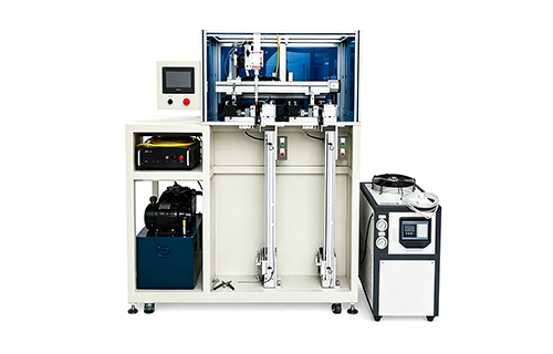
Resistance Welding Machine for Vapor Chamber Production
1. What Is a Resistance Welding Machine?
A Resistance Welding Machine joins metal components by generating heat through electrical resistance while applying mechanical pressure. The equipment controls the welding current, welding time, and electrode force to create a joint between the workpieces.
Unlike many arc welding processes, resistance welding typically does not require filler metal. Instead, electrical current generates localized heat at the joining interface. Pressure helps maintain contact and form the joint.
Resistance welding includes several processes, such as spot welding, seam welding, projection welding, and butt welding. Each method serves different joint geometries and production requirements.
For thermal management manufacturing, equipment selection depends on the component design. Vapor chambers and heat pipes often use thin copper or copper-alloy shells. These products require careful control of heat input and joint consistency.
A resistance welding machine designed for suitable thermal components can support repeatable joining operations. For vapor chambers, continuous seam welding may be particularly relevant when the design requires a sealed perimeter.
However, not every resistance welding machine suits every vapor chamber. Manufacturers must confirm the welding method, electrode arrangement, material compatibility, and sealing requirements before selecting equipment.
2. How Resistance Welding Works
Resistance welding relies on electrical resistance to generate localized heat. The machine applies current through the workpieces while electrodes or other contact components maintain pressure.
However, actual welding behavior also depends on contact resistance, material properties, electrode geometry, and heat transfer.
2.1 Workpiece Positioning
First, the operator or automated handling system positions the metal components. The fixture keeps the joint aligned throughout the welding cycle.
Accurate positioning helps maintain consistent contact conditions. It also reduces the risk of uneven welds caused by movement or misalignment.
2.2 Applying Electrode Force
The machine applies pressure through the electrodes or welding mechanism. The force establishes electrical contact and helps control the joint during heating.
Too little force may cause unstable contact, excessive local heating, or expulsion. Too much force may reduce interface resistance or deform thin components.
Therefore, manufacturers should determine the appropriate force through process development and testing.
2.3 Applying Welding Current
The power system supplies controlled current to the workpiece. Electrical resistance generates heat near the joint.
The machine’s controller manages current duration and, depending on its configuration, other parameters such as current profile and pulse sequence.
The goal is to create a suitable joint without excessive deformation or damage to surrounding material.
2.4 Holding and Cooling
After the current stops, the machine may maintain force while the joint cools and solidifies. The exact sequence depends on the welding method and equipment design.
Proper control helps produce repeatable results. Electrode condition and cooling also affect process stability during continuous production.
2.5 Inspecting the Joint
After welding, manufacturers inspect the joint against established criteria. Inspection may include visual checks, dimensional measurements, destructive testing, or leak testing when the component requires a sealed cavity.
For vapor chambers, the appropriate verification method depends on the sealing design and product specifications.
3. Why Resistance Welding Matters in Vapor Chamber Manufacturing
3.1 Supporting Thin Metal Components
Vapor chambers use thin metal plates to create a compact sealed structure. Manufacturers must join these plates without introducing unacceptable deformation.
A suitable resistance welding process can concentrate heat around the joining interface. Nevertheless, thin copper components can present challenges because copper conducts electricity and heat efficiently.
The equipment and process must therefore match the material, thickness, joint geometry, and required weld characteristics.
3.2 Maintaining Sealing Integrity
A vapor chamber relies on a sealed cavity containing a working fluid. The cavity supports evaporation and condensation, which move heat from one region to another.
A defective perimeter joint may allow gas to enter or working fluid to escape. Such defects can affect product performance and reliability.
For this reason, manufacturers must distinguish between a joint that provides mechanical attachment and one that meets the required sealing specification.
Continuous resistance seam welding may suit certain vapor chamber designs because roller electrodes can create a continuous joint along a programmed path. Suitability depends on the actual chamber construction and validated process capability.
3.3 Improving Production Repeatability
Manual joining operations can introduce variation in positioning, pressure, and heat input. Controlled welding equipment helps standardize these conditions.
Manufacturers can establish qualified recipes for different product models. They can then monitor production and investigate deviations when defects occur.
However, repeatability depends on more than the machine. Consistent incoming materials, clean surfaces, suitable fixtures, electrode maintenance, and operator training remain important.
3.4 Supporting Automated Manufacturing
Resistance welding can integrate with fixtures, handling systems, and production controls. This makes it relevant to high-volume manufacturing where consistent cycle times matter.
For thermal management products, the complete production process may include component preparation, internal structure assembly, welding, vacuum processing, filling, and testing.
The welding machine should fit this broader workflow rather than operate as an isolated piece of equipment.
4. Main Types of Resistance Welding
Different resistance welding methods address different joint requirements. Manufacturers should select the process according to the product’s structure and intended function.
Welding type | Working principle | Typical application |
Spot welding | Electrodes create localized weld points | Sheet-metal assemblies and electrical components |
Seam welding | Roller electrodes form a continuous or overlapping weld | Suitable sealed or continuous sheet-metal joints |
Projection welding | Designed projections concentrate current and force | Components requiring one or multiple localized welds |
Butt welding | Current and force join components at their ends | Wires, rods, bars, and compatible end-to-end joints |
These processes share the principle of resistance heating, but their electrode designs and joint geometries differ.
4.1 Spot Welding
Spot welding joins metal sheets at discrete locations. It suits applications where individual weld points provide sufficient mechanical strength.
However, separate spot welds do not automatically create a continuous airtight perimeter. Manufacturers should not substitute spot welding for continuous sealing unless the product design specifically supports that approach.
4.2 Seam Welding
Seam welding commonly uses rotating wheel electrodes to create a series of overlapping welds. With appropriate process settings, these welds can form a continuous seam.
This method may suit vapor chamber shells that require perimeter joining. The machine must provide suitable electrode access, consistent force, and controlled current along the complete seam.
The joint must still pass the relevant inspection and leak testing. A continuous-looking seam does not, by itself, prove that the chamber is leak-tight.
4.3 Projection Welding
Projection welding concentrates current at designed raised features. It can create multiple joints during one cycle when the part geometry supports this method.
Its suitability depends on the component design and the required joint characteristics. It is not automatically appropriate for thin vapor chamber perimeter sealing.
4.4 Choosing Between Seam Welding and Laser Welding
Resistance seam welding and laser welding use different energy delivery methods.
Resistance seam welding generates heat through current flowing across the joint under electrode pressure. Laser welding delivers concentrated optical energy to the joining area.
The better choice depends on material thickness, geometry, accessibility, production volume, sealing requirements, and process validation.
Internal link opportunity: 🔗 Laser Welding Machine for Vapor Chamber.
5. Key Features of a Resistance Welding Machine
When evaluating a Resistance Welding Machine, manufacturers should review the complete mechanical and electrical system.
5.1 Welding Current Control
Current control determines how much electrical energy enters the joint. A suitable controller should support the process window required by the material and component design.
Buyers should ask about current adjustment, repeatability, monitoring, and available welding schedules.
5.2 Electrode Force Control
The force system keeps the workpieces in contact during the welding cycle. Depending on the machine, it may use pneumatic, servo-driven, or other mechanisms.
The best option depends on the required force range, positioning accuracy, cycle time, and product sensitivity.
5.3 Welding Time Control
Welding time influences the amount of heat generated. A suitable controller should provide the timing resolution needed for the application.
Some systems also support multi-stage current profiles. These may help engineers optimize difficult joints, depending on the power supply and controller.
5.4 Electrode and Fixture Design
Electrode shape affects current distribution and contact pressure. Fixture design determines how securely the workpiece sits during welding.
For thin copper components, the electrode arrangement must suit the product geometry and material behavior.
Buyers should request a trial using actual parts rather than relying on general-purpose machine specifications.
5.5 Cooling and Thermal Management
Resistance welding generates heat in the electrical system, conductors, and electrodes. Suitable cooling helps maintain stable operation.
Cooling requirements vary by machine type, duty cycle, current level, and power supply. The American Welding Society highlights the importance of selecting appropriate cooling capacity for resistance welding equipment.
5.6 Process Monitoring
Depending on the machine configuration, monitoring may include welding current, voltage, electrode force, displacement, or other process indicators.
These measurements can help identify deviations. However, monitoring only adds value when the signals relate meaningfully to the actual joint quality and the manufacturer has defined suitable limits.
6. Benefits for Thermal Management Manufacturing
6.1 Controlled Heat Generation
Resistance welding generates heat at the joint through electrical resistance. With suitable settings, manufacturers can create localized heating without using filler metal.
The result depends on material properties, contact conditions, electrode design, and process control.
6.2 Efficient Production Cycles
Resistance welding can offer short welding cycles and support automated production. This can benefit manufacturers producing large quantities of compatible components.
Actual output depends on loading, positioning, welding time, cooling, inspection, and changeover requirements.
6.3 Reduced Consumable Requirements
Many resistance welding processes do not require filler wire, flux, or shielding gas. This can simplify certain production workflows.
However, electrodes and other machine components still require inspection and periodic replacement.
6.4 Repeatable Manufacturing Conditions
Programmed welding schedules help standardize current, force, and timing. This can reduce process variation when manufacturers maintain consistent materials and equipment conditions.
Production records also make it easier to compare batches and investigate defects.
6.5 Potential for Automation
Resistance welding equipment can work with automatic handling and production-line controls.
For thermal component manufacturers, automation may reduce repetitive manual work and improve material flow. The final benefit depends on the level of integration and the stability of upstream operations.
7. Applications in Vapor Chamber and Heat Pipe Production
7.1 Vapor Chamber Perimeter Welding
Certain vapor chamber designs require a continuous joint around the outer shell. A suitable resistance seam welding system may perform this operation when the materials and geometry support the process.
The system must accommodate the chamber dimensions and provide consistent electrode contact around the sealing path.
Because vapor chambers rely on a sealed internal cavity, manufacturers should verify the completed joint through appropriate quality checks.
Internal link opportunity: 🔗 Vapor Chamber Production Line.
7.2 Heat Pipe Component Joining
Heat pipe manufacturing may involve joining metal components at selected stages. Resistance welding can suit compatible joints, depending on their shape, material, and required sealing performance.
The process sequence varies by design. Manufacturers should confirm whether resistance welding fits the intended joining operation or whether another welding method is more appropriate.
Internal link opportunity: 🔗 Heat Pipe Production Line.
7.3 Thermal Component Assembly
Some thermal management assemblies include metal brackets, supports, tabs, or other conductive parts.
Resistance spot or projection welding may suit selected assembly operations. The correct method depends on the required strength, electrical properties, appearance, and production volume.
7.4 High-Volume Industrial Manufacturing
Resistance welding also serves applications beyond vapor chambers, including automotive parts, appliances, and sheet-metal assemblies.
These examples demonstrate the process’s flexibility, but equipment designed for general industrial applications may not meet the specialized requirements of thin thermal components without appropriate adaptation.
8. How to Choose the Right Resistance Welding Machine
Before purchasing equipment, define the application and acceptance requirements.
8.1 Identify the Welding Method
Start by confirming whether the application needs spot welding, seam welding, projection welding, or another joining process.
For vapor chamber perimeter sealing, discuss whether continuous resistance seam welding is suitable for the actual shell design.
8.2 Confirm Material and Thickness
Provide the supplier with the metal type, thickness range, dimensions, and surface condition.
Copper and copper alloys can require careful process development because of their high electrical and thermal conductivity.
The supplier should assess compatibility using representative materials.
8.3 Define the Joint Requirements
Explain whether the joint must provide mechanical strength, continuous sealing, or both.
For a sealed thermal component, define the relevant leak-test method and acceptance criteria. Do not rely on appearance alone.
8.4 Estimate Production Capacity
Calculate the required output per shift and consider the full cycle.
Include loading, positioning, welding, cooling, inspection, and unloading. This provides a more realistic capacity estimate than welding time alone.
8.5 Review Control and Monitoring Options
Consider whether the application needs recipe storage, process monitoring, automatic fault alerts, or production data records.
These features may be especially useful when the factory manufactures multiple product models or operates under strict quality requirements.
8.6 Evaluate Maintenance and Support
Ask about electrode maintenance, cooling requirements, spare parts, operator training, and technical support.
A machine’s total cost includes more than its initial purchase price. Maintenance time, consumables, downtime, and scrap rates can also affect long-term operating costs.
8.7 Request Sample Welding
A sample trial helps determine whether the proposed machine can meet the product requirements.
Use actual workpieces and representative production conditions. Inspect the resulting joint and perform the required mechanical or leak tests.
Only approve the configuration after the results meet agreed acceptance criteria.
9. Integrating Resistance Welding into a Production Line
A resistance welding machine should fit the complete manufacturing sequence.
For vapor chamber production, a possible workflow includes:
- Material preparation: Prepare the metal plates and inspect their dimensions.
- Surface cleaning: Remove contamination that could affect electrical contact or joint formation.
- Internal assembly: Install the wick structure and other required components.
- Positioning: Load the parts into the welding fixture.
- Resistance welding: Apply the validated current, force, and timing sequence.
- Initial inspection: Check the joint appearance and component dimensions.
- Vacuum processing and filling: Complete the required internal processing according to the product design.
- Final closure: Seal any remaining opening using the specified process.
- Leak testing: Verify sealing integrity where required.
- Thermal performance testing: Confirm the completed component meets its performance requirements.
The exact order depends on the product architecture. Some designs require different welding, evacuation, filling, and final-sealing sequences.
For factories planning a complete system, relevant internal links may include 🔗 Vapor Chamber Vacuum Filling & Welding Machine, 🔗 VC Water Bath Bubble Leak Tester, and 🔗 Vapor Chamber Thermal Performance Tester.
Link these anchors to the corresponding live product pages on linkthermal.com, if available.
10. Weld Quality Control and Maintenance
10.1 Monitor Current, Force, and Time
Current, electrode force, and welding time are central process variables.
Record the approved settings and define how operators should respond to deviations. Where appropriate, use process monitoring to detect unusual cycles.
10.2 Inspect Electrodes Regularly
Electrode wear and contamination can change the contact area and affect current distribution.
Inspect the electrodes according to the machine supplier’s recommendations. Maintain their geometry and replace worn components when necessary.
10.3 Maintain Cooling Systems
Follow the specified cooling requirements for the transformer, conductors, electrodes, and power electronics.
Check coolant flow, temperature, and any monitoring alarms. Inadequate cooling can destabilize production and damage equipment.
10.4 Verify Joint Quality
Choose inspection methods based on the application. These may include visual inspection, dimensional checks, destructive testing, and leak testing.
For sealed vapor chambers, select a leak test with suitable sensitivity for the product’s requirements.
10.5 Establish a Maintenance Schedule
Create a maintenance plan covering electrical connections, moving parts, fixtures, cooling systems, and control equipment.
Document inspections and repairs. Consistent maintenance reduces unexpected downtime and helps preserve process stability.
11. Common Welding Problems and Solutions
Problem | Possible cause | Recommended action |
Inconsistent weld strength | Variation in current, force, or contact conditions | Review the process window and material consistency |
Excessive indentation | Excessive force, heat, or unsuitable electrode geometry | Adjust the settings and inspect the electrodes |
Spatter or expulsion | Unstable contact or excessive heat generation | Review current, force, surface condition, and timing |
Incomplete joint formation | Insufficient heat or unsuitable contact conditions | Validate current, time, force, and fixture alignment |
Workpiece deformation | Excessive localized heating or poor support | Optimize the welding sequence and fixture design |
Electrode overheating | Inadequate cooling or excessive duty cycle | Check cooling flow and operating conditions |
Intermittent leakage | Inconsistent seam formation or local joint defects | Inspect the sealing path and validate the process |
Variable results between batches | Material variation, electrode wear, or uncontrolled settings | Standardize inputs and monitor process parameters |
These problems can have several causes. Engineers should investigate them systematically rather than changing multiple parameters at once.
For vapor chamber production, the final acceptance decision should reflect both the joint’s intended function and the relevant inspection results.
12. Why Consider Linkthermal?
Choosing a Resistance Welding Machine for thermal components requires careful matching between equipment capability and product design.
Linkthermal is the brand associated with this website’s thermal manufacturing equipment content. For a potential application, buyers should first define the required welding process, product dimensions, material properties, and sealing criteria.
Before discussing an equipment configuration, prepare:
- Product drawings and dimensions
- Material type and thickness
- Required joint geometry
- Target production capacity
- Mechanical strength or sealing requirements
- Existing vacuum processing and filling methods
- Inspection and traceability requirements
This information helps establish whether resistance welding is suitable for the application and what equipment features deserve priority.
For a broader production solution, consider linking to the relevant Vapor Chamber Production Line, Vapor Chamber Vacuum Filling & Welding Machine, and VC Water Bath Bubble Leak Tester pages, if available.
Visit Linkthermal to explore thermal manufacturing equipment and related production solutions.
13. Frequently Asked Questions
13.1 What is a Resistance Welding Machine?
A Resistance Welding Machine joins metal components by generating heat through electrical resistance while applying pressure. It controls important process variables such as current, time, and electrode force.
13.2 What materials can resistance welding join?
Resistance welding can join many metals, including compatible steel, stainless steel, copper alloys, and other conductive materials.
Suitability depends on the material combination, thickness, joint design, electrode arrangement, and machine capability.
13.3 Can resistance welding be used for vapor chambers?
It can be suitable for certain vapor chamber joining operations. Continuous resistance seam welding may fit some perimeter-sealing designs.
However, manufacturers must validate the process against the chamber material, geometry, and leak-tightness requirements.
13.4 What is the difference between resistance seam welding and spot welding?
Spot welding creates individual weld points. Seam welding uses rotating electrodes to form a continuous or overlapping weld along a path.
For components requiring a continuous sealed boundary, seam welding may be more suitable than isolated spot welds.
13.5 Does resistance welding require filler metal?
Most conventional resistance welding processes do not require filler metal. The joint forms through localized resistance heating and applied pressure.
This can simplify material handling for suitable manufacturing applications.
13.6 How do manufacturers control weld quality?
They control current, welding time, electrode force, surface condition, fixture alignment, and electrode wear.
Manufacturers may also monitor process signals and verify the finished joint through appropriate inspection and testing.
13.7 Is resistance welding suitable for copper?
It can be, but copper’s high electrical and thermal conductivity creates specific process challenges.
Equipment selection and parameter development should account for the copper grade, thickness, joint design, and required production conditions.
13.8 How should buyers evaluate machine capacity?
Evaluate the complete production cycle, including loading, positioning, welding, cooling, inspection, and unloading.
A sample trial using representative parts provides a more reliable basis for capacity planning.
13.9 Can resistance welding guarantee an airtight vapor chamber?
No welding method guarantees airtightness solely because the equipment completed its cycle.
Manufacturers must validate the joining process and verify sealing integrity using an appropriate leak-testing procedure.
13.10 What information should buyers provide when requesting a quotation?
Provide drawings, material specifications, thickness ranges, joint requirements, production targets, and inspection criteria.
For vapor chambers, also describe the intended sealing path and the required leak-testing method.
14. Conclusion
A Resistance Welding Machine can provide a controlled and repeatable method for joining compatible metal components. It uses electrical resistance and mechanical pressure to form joints without the need for conventional filler materials.
In thermal management manufacturing, resistance seam welding may suit selected vapor chamber designs that require continuous perimeter joining. Nevertheless, the correct process depends on material properties, component geometry, sealing requirements, and production targets.
Manufacturers should evaluate current control, electrode force, cooling, fixture design, and process monitoring before purchasing equipment. They should also validate weld quality through representative sample testing.
For vapor chamber and heat pipe manufacturers, the best solution is one that fits the entire production process. Welding, vacuum processing, filling, leak testing, and thermal verification should work together to support consistent product quality.
Visit Linkthermal to explore relevant thermal manufacturing equipment and assess which solution matches your application.